Contents
The Formation Platforms
Introduction
This project is the application of UAV entertainment, which is specifically LED light show. This is also one of the main applications in the current drone market, since the mini-sized drones are mostly used as an entertaining toy, such as selfie cameras or LED toys instead of indsutrial use. The recent news show several companies like Yihang, Intel or some research agents did UAV light shows with a large swarm of drones up to 500 or even 1000.
Before the Intel 500 demos, the NUS UAV team also realized a 16-set quadcopter outdoor light show with aid of differential GPS for very accurate positioning. Below video is the show, where the prime minister Lee Hsien Loong appeared.
The project is for the opening ceremony of Rotorcraft Asia 2017, which will be held on April 18. The stage will be in a certain stadium, where no GPS signal is available. For indoor positioning, we use ultra-band width (UWB) system. The platform is also mounted an ultra-bright LED matrix pad for configurable color and brightness light.
Flight Controller
All the flight controller used in my projects is the same (see link);
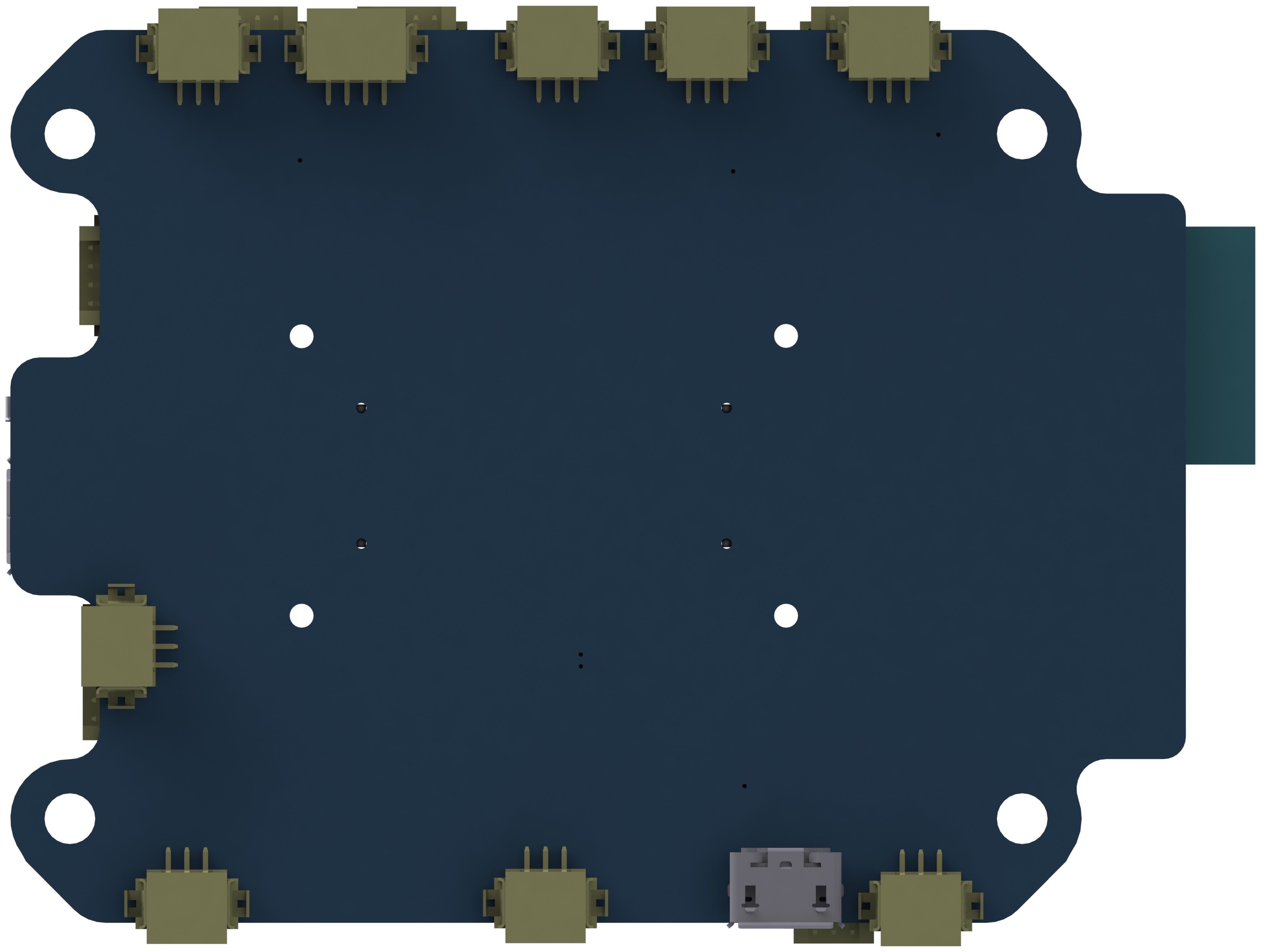
Flight Controller Expansion Board
- The board integrates necessary peripherals: SD card for data logging, serial to Wi-Fi module for data-link, serial to USB device for debugging, LED controller, power rails and IO ports.
- The LED controller uses Arduino as platform and Neopixel libraries for light control and pattern design.
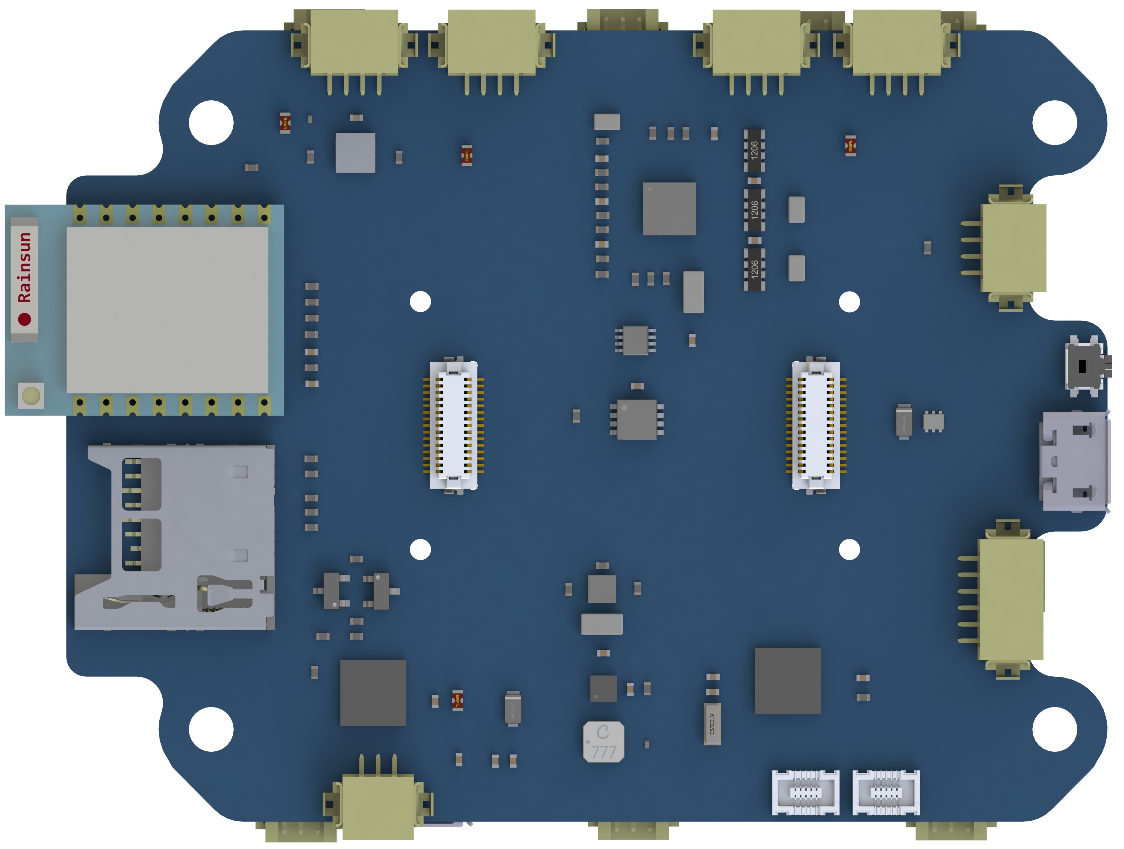
Power Expansion Board
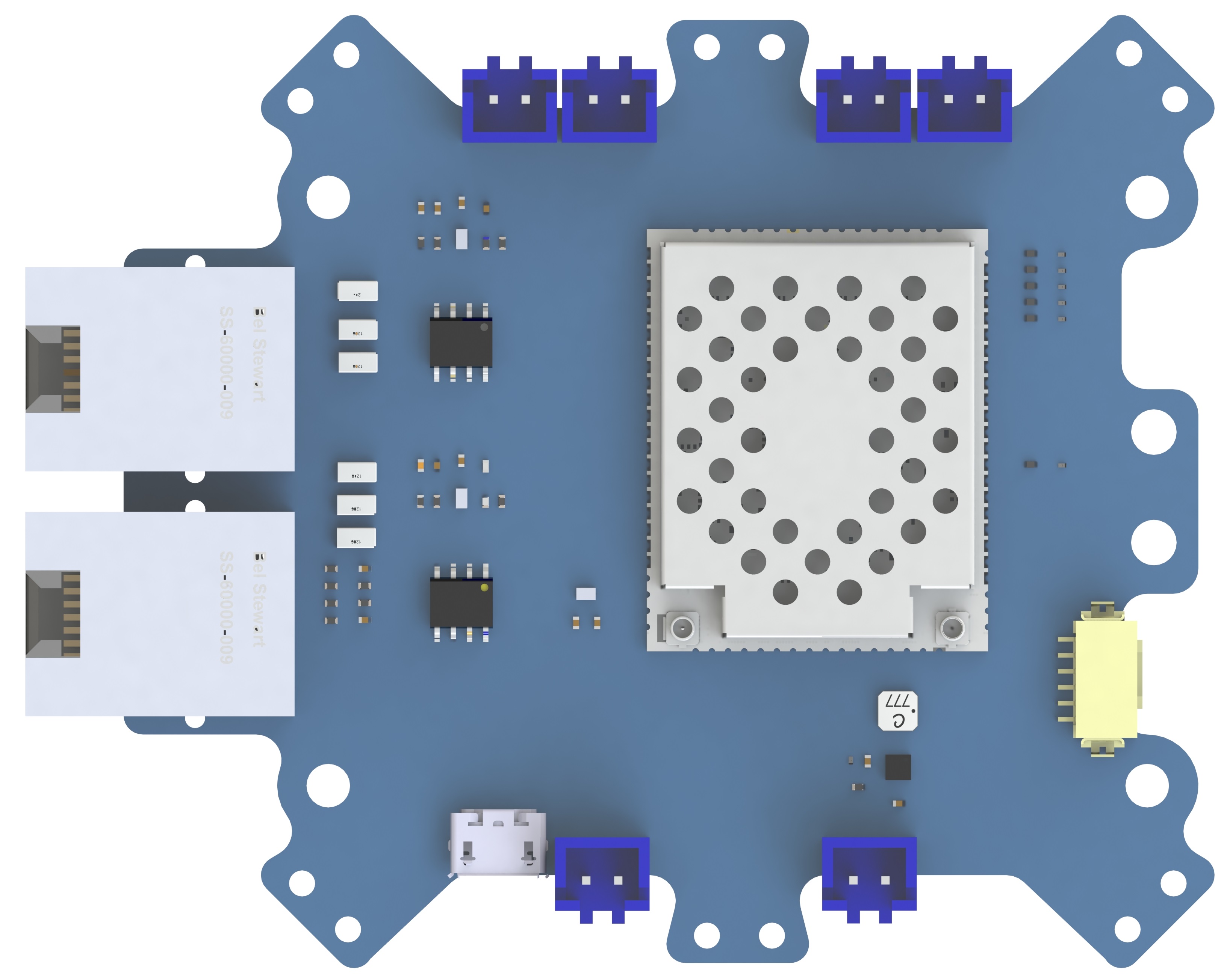
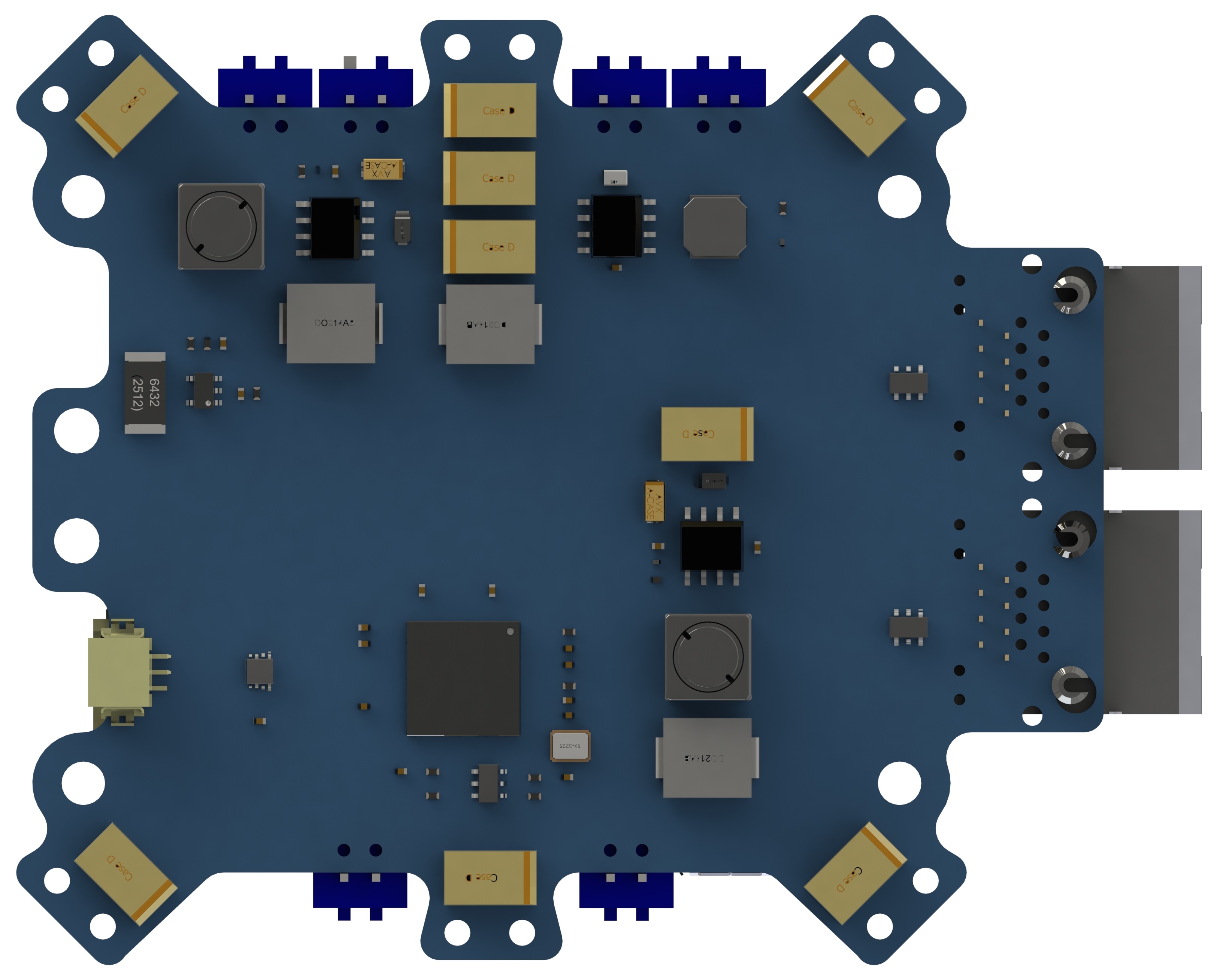
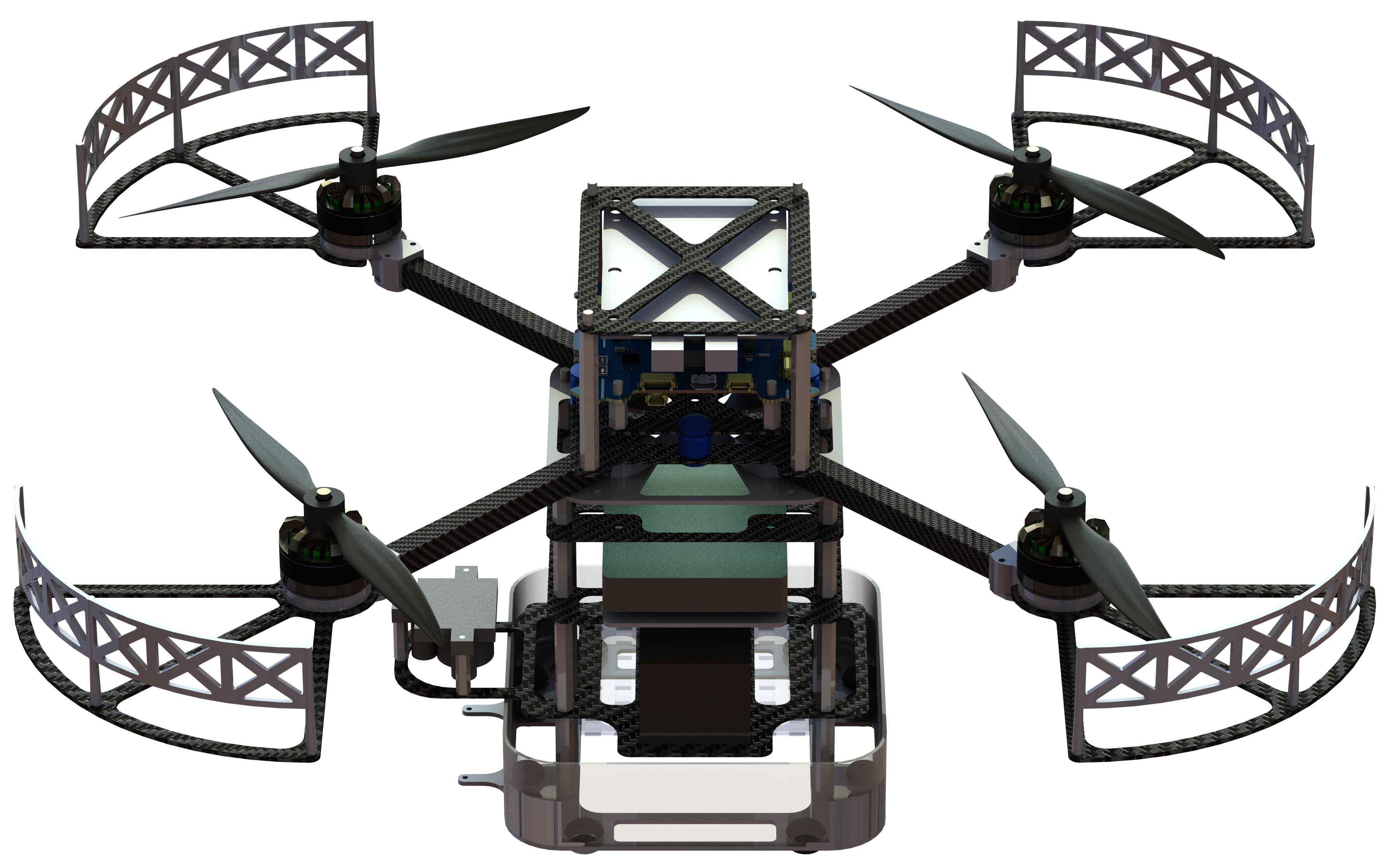
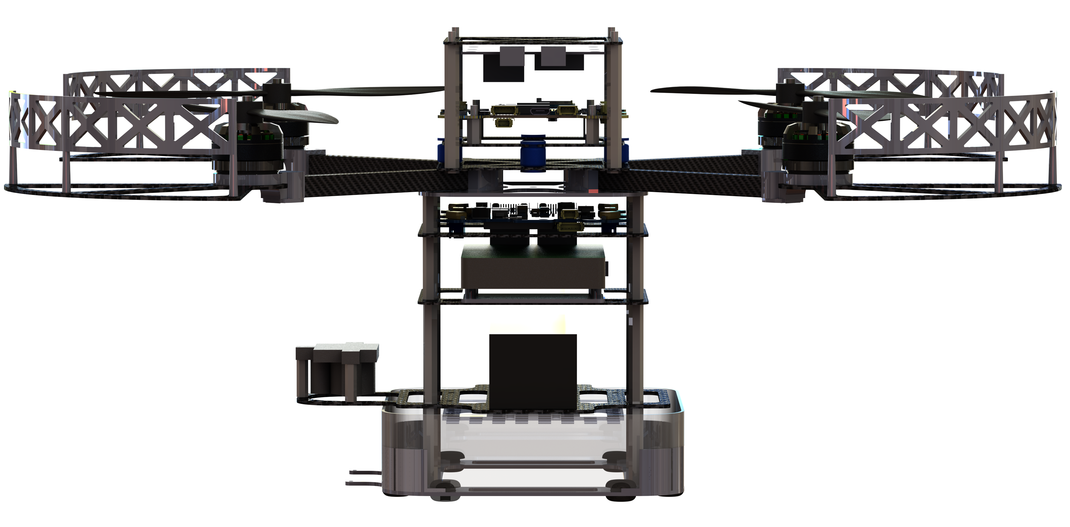
- This platform adopts dual-board design in order to reduce the foot-print, as a quad-rotor helicopter with dimension limitation confines its space left for avionics;
- Another reason for dual board design is that the onboard magnetometer is prone to be interfered by large current, if there is only one extension board, where large current drained by ESCs is inevitable. Dual board design separates large current and megnetic components with one mu-metal slice sheet placed in between if necessary;
- This power extension board includes: dual 5V power output, one 12V power output, one MicroHard pDDl data and video link system, 2 ethernet ports for connecting Up-board as a remote control display port as well as another device (laser scanner / UWB ranging module), power distributions.
Other Modules
- Dampers: dampers are necessary to reject high freqency vibrations. Silicon ball dampers are used and tested.
- UWB ranging modules: we selected the PulsOn 440 from Time Domain as the ranging modules, whose max communication range is up to 200 m, which is enough for indoor demo use.
- Up-board: the upper level CPU used for path planning and trajectory generation. Coordinates calculation for a certain tag given a random setup of anchors is also processed in the CPU.
- LED device: we select Neopixel LED matrix for light display for its high lumin parameter and the color and brightness can be configured to desired values.
Below is our first manual flight test, where we conducted outside our lab. It can be seen from the video vibration exists at the take-off period. This could be the gain tuning problem.
Autonomous Navigation
This is a milestone for fully autonomous control of the UWB version quad-copter designed for this project. We have mounted several VICON markers on the platform and placed in the VICON environment. In order to test the performance of the implemented control law as well as calibrate the UWB positioning accuracy, we first do the auto hovering in VICON room and further with a simple path.
Problems and Solutions
- Attitude estimation error: this was caused by the temperature effect on the MPU9250 series motion sensors. The accelerometer readings will be affected by the varying temperature on the start-up phase. This was solved by the adding a temperature curve compensation of the accleration measurement;
- UWB ranging error: this was mainly caused by setup of the UWB anchors. The positions and distance between each other affect the final ranging accuracy.
- UWB estimation error: this was introduced by low update rates of UWB range information as well as the extended Kalman Filter motion model. The motion model was a constant velocity model which did not concern the dynamics of the drones. We added the acceleration information into the motion model and improved the update frequency of the overall range request loops, the accuracy was also improved to 5cm and latency was limited within 200ms.
- Magnetometer interference problem: this was caused by the large current interference to the magnetic field around the magnetometer. The final platform uses shielding materials above the power regulation board and eventually mitigated the effect.
Actual Performance
It was the actual day for the UMSA openning ceremony. We have been testing the whole formation drones system for the last two weeks in Changi Exhibition Center, the Aviation Park beside the sea. The UWB signal is very stable and reliable in the demo hall area with the full dimension around 15m X 15m X 7m. The formation drones was reduced to 6 sets from 10 sets due to the confined area and signal bandwidth capability. The formation shape and path designed for each drone is based on the music rhythm and light will also changes their patterns and color accordingly.
The patterns include a formal square shape, a figure eight rotation, a random flight, a heart shape, leader and followers shape. With the starry night background and the music, the overall effect is really touching and exciting.