Contents
Traditional Scalar Control
For a simple brushed motor, where the rotational motion is completed by the electrical brush, no complex ESC is necessary, especially for small brushed motors. However, for a brushless DC motor or for a permanent-magenetic sychronized motor (PMSM), the electrical speed control (ESC) is definitely necessary, as there is no switching mechanism inside the motor and the rotational motion is done by the external circuits.
Traditional Method
A BLDC can always be modeled as a R-L circuit, where each phase has its own resistance and inductance. Sometimes, the stators are the magent and the rotor is the wire coil and sometimes the case is opposite. In drone area, we often use the outrunner, where the wire coil is the rotor and the permanent magnet is the stator. For such a configuration, each kind of BLDC, large ones or small ones can often be simplified as a 3-phase system with a star shape connection, where larges ones has more poles and small ones got less.
Scalar Method
COTS ESCs are implemented with the most direct way to control the rotor position, scalar control method. Each conducting interval is 120 degree by electical angle, which follows the sequence as AB-AC-BC-BA-CA-CB to make sure tha the magnetic filed generated by the windings keeps changing 60 degree each commutation step, yielding a constant rotating direction.
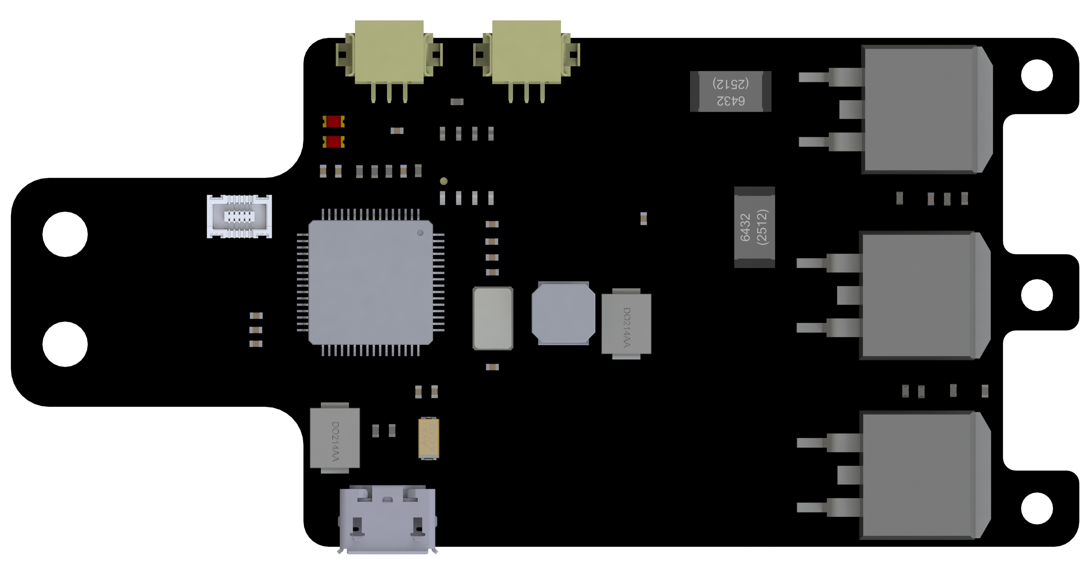
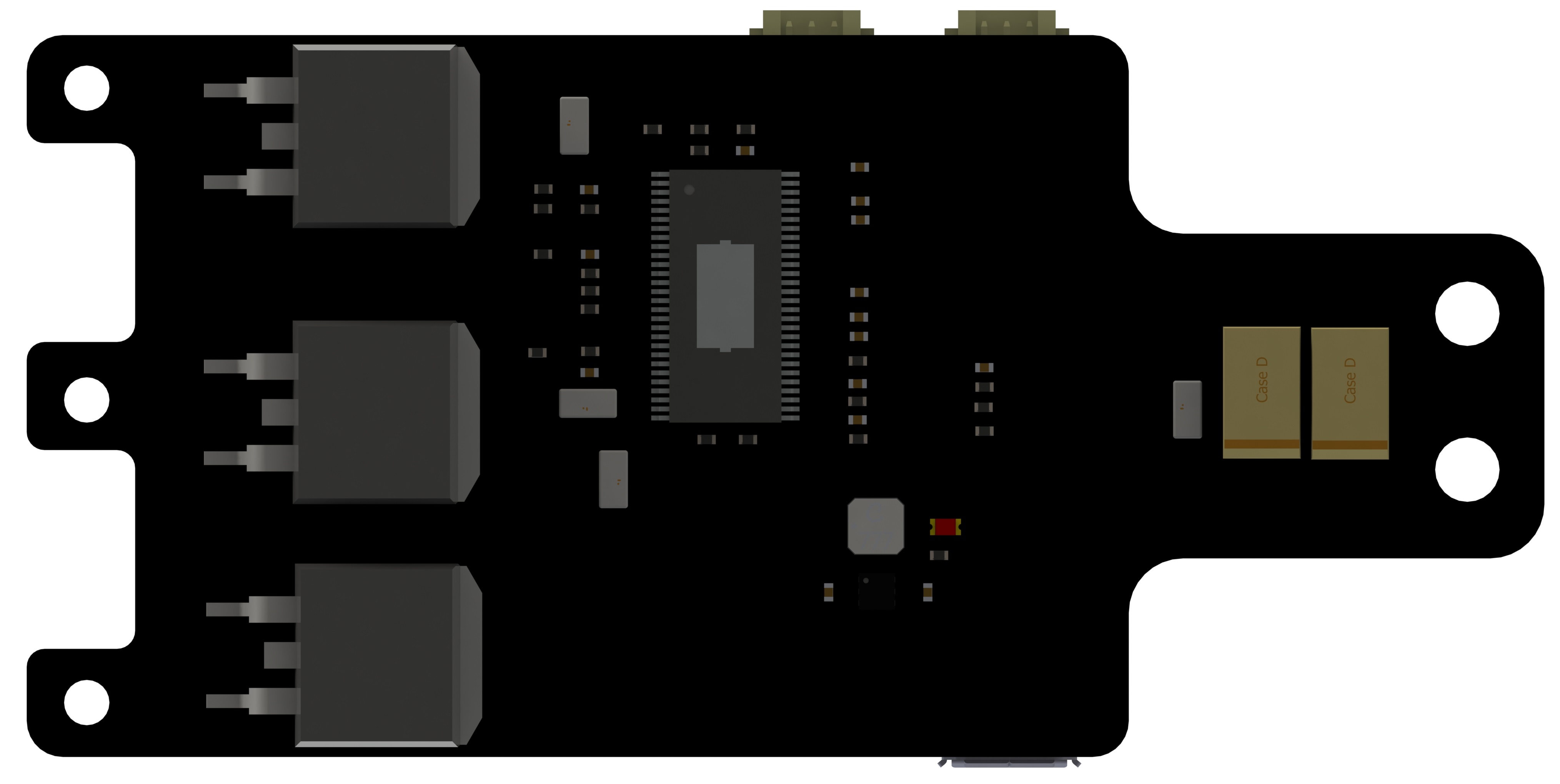
The core technology inside is the knowledge of the rotor position, i.e. the exact sector the rotor currently lies in. The technique used to solve this is back-EMF detection, which provides the rotor current position thorugh an indirect way. Below ESC is implemented with this method. Besides the basic idea of scalar method, several features were added to the ESC:
- clock-wise rotational motion;
- counter-clockwise rotational motion;
- brake in any rotating state;
- PWM and I2C control;
Pros:
- Simplicity in circuit design and firmware structure;
- Low cost;
- High robustness and reliability; Cons:
- Low accuracy and low efficiency.
Field Oriented Control
The field oriented control is often used for PMSM motor and has not been comercially applied on BLDC, since the back-EMF generated by PMSM is a sinusoidal shape, while for BLDC is a trapezoidal shape. However, the FOC is still able to be applied on BLDC, yielding a lower efficiency than its application on PMSM.
Vector Method
Normally the proces of FOC can be modularized into five blocks:
- Clarke transformation: conversion of stator winding current or voltage from 3-phase rotating coordinate to 2-phae rotating corrdinate;
- Park transform: transformation from time-variant system to a time-independent system direct-quadrature, which is known as the core of FOC;
- Controls: control process regarding with the decoupled time-invariant system, where a simple PI controll can be used;
- Formulation of Control: the control output can be reformulated to speed and torque components and fed to the reverse Park transformation;
- SVM: space vector modulation, generating PWM signal to drive the motor, which is the back-end process.
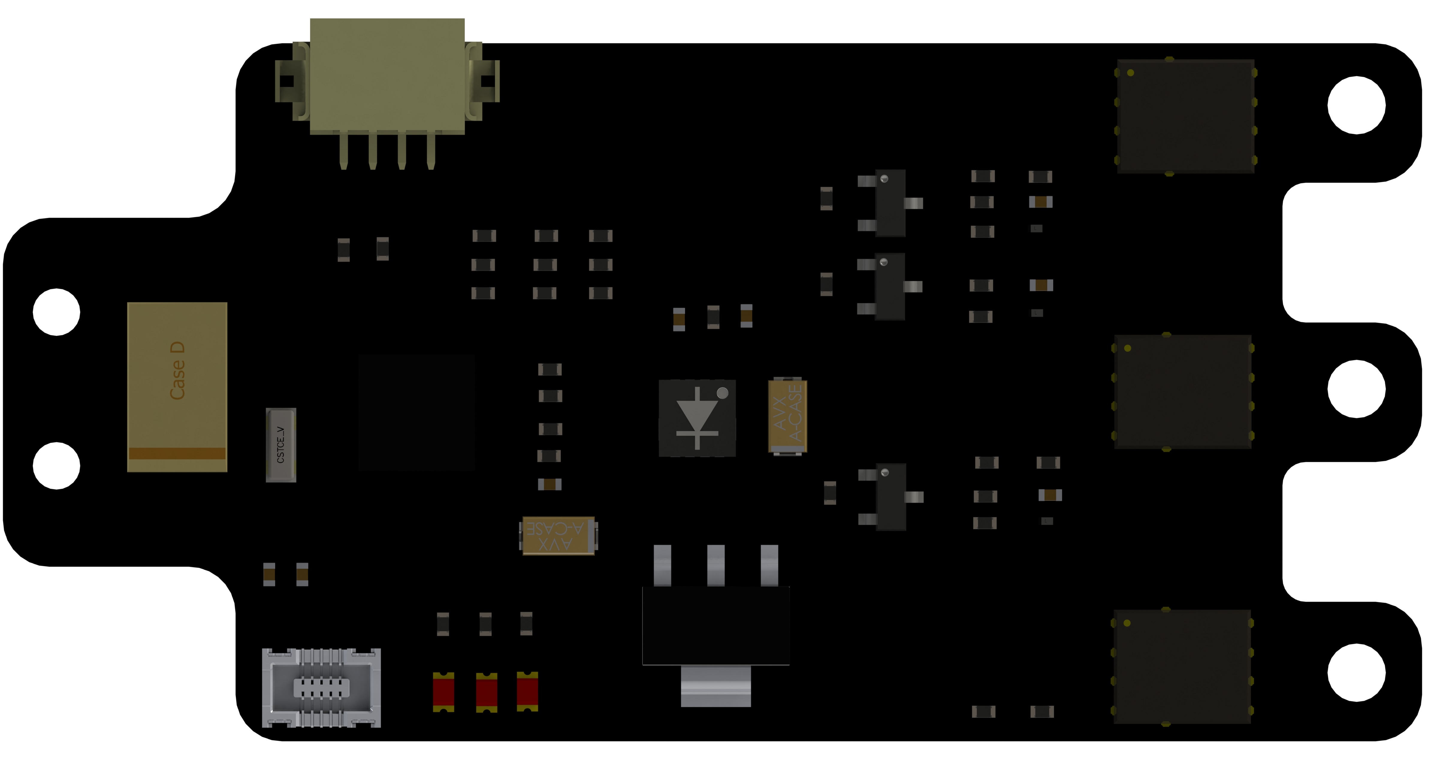
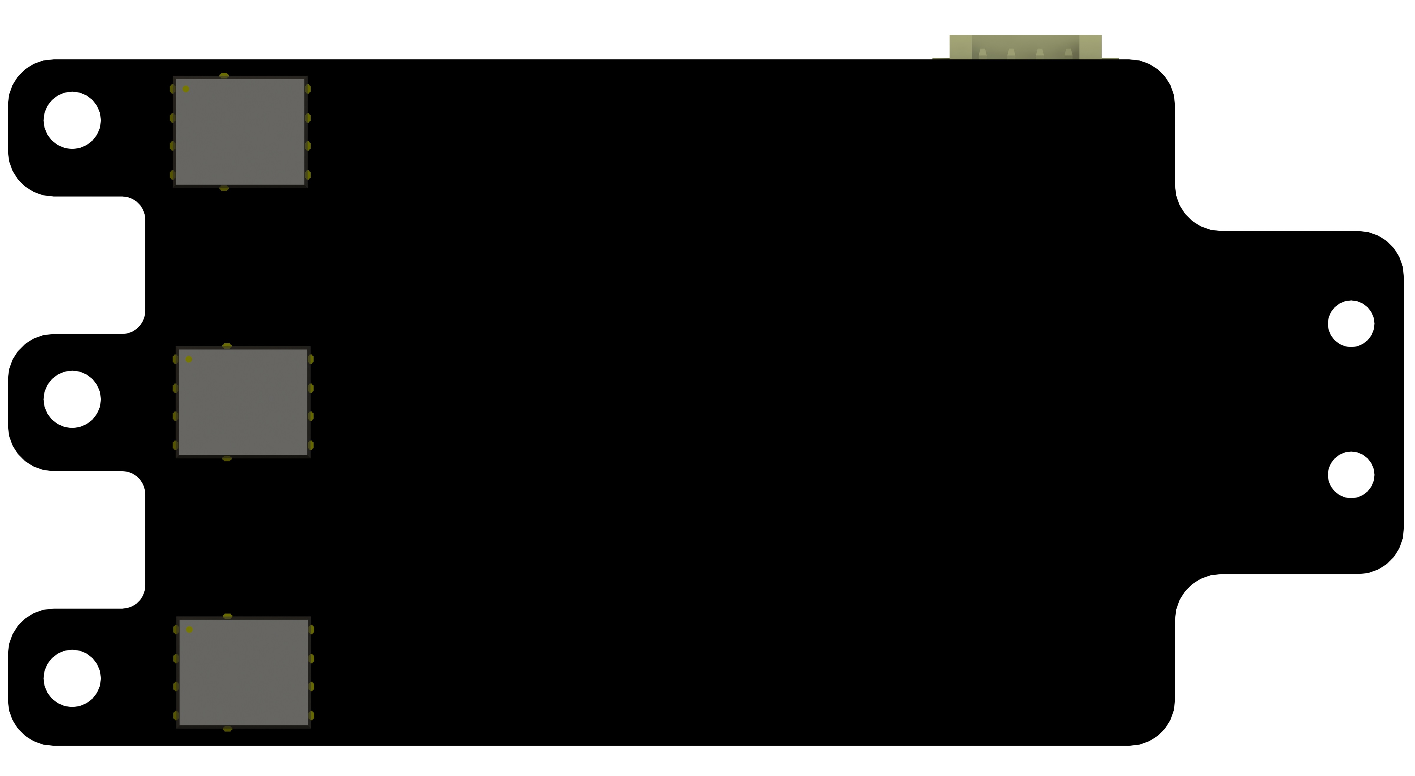
Below is the module designed for a FOC based ESC, which is still under development presently.