Contents
Project Overview
The project funded by DSO National Laboratories, aims to develop an ultra compact MAV within 100 gram in mass and 8 minutes flight time. The developed MAV is able to safely navigate through indoor environment and complete autonomoously necessary flight missions. The main tasks of this project involve the constructin of the custom-made aerial vehicles, development of an embedded avionic system, modeling of athe MAV system and design of robust flight controllers. The systematic design methodology and innovative technologies will be utilized to optimize the vehicle itself and the avionic system to fulfill the required specifications. A robust flight controller will be designed and implemented for the MAV in terms of the identified model. The entire system of the MAV will be tested in the actual flight.
Achievements of the project
- Systematic and optimal design methodologies of the MAV was proposed to fulfill the demanding requirements of MAV, including light weight, sufficient flight time and mission tasks. The design methodologies, integrated with CAD technologies and aerial dynamic simulation approaches, were investigated to iteratively optimize the selection and design of each component of the MAV, including the mechanical parts of aerial vehicles, and electrical devices of the avionics.
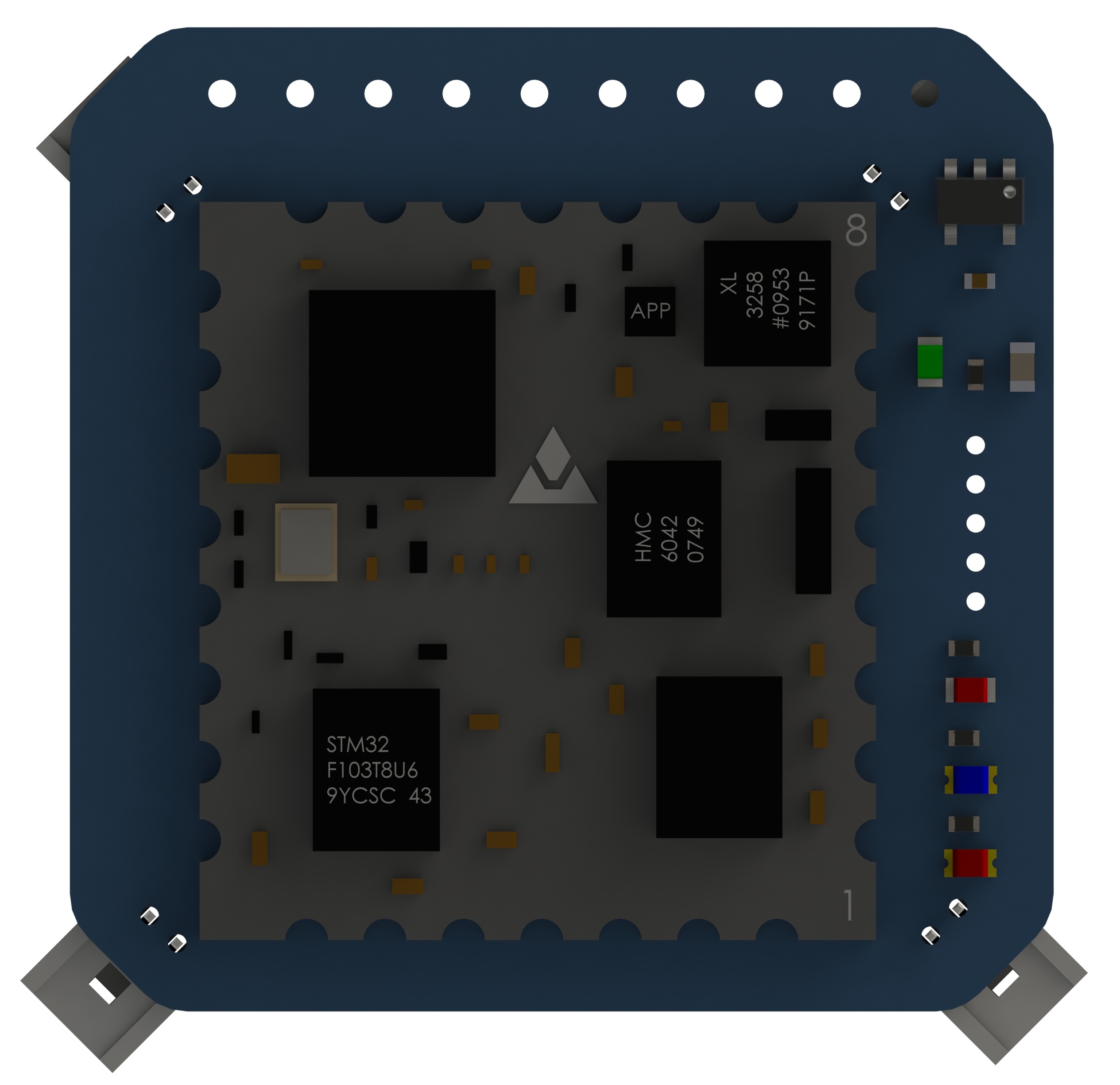
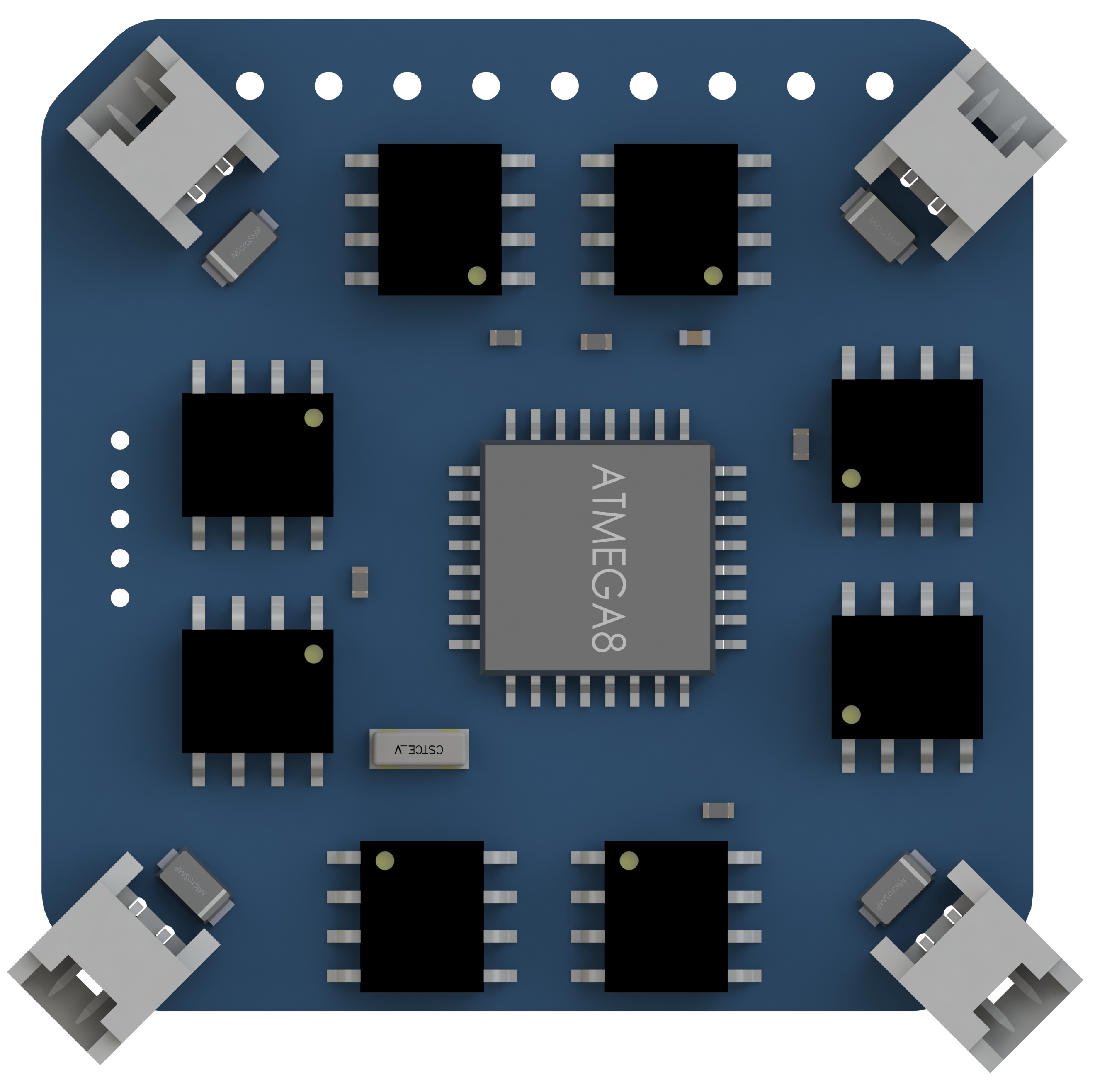
- The avionics for MAV were developed, including the processing units, navigation sensors, vision sensors, peripheral mission-required sensors, and wireless communication modules. The final components were with light weight, low power consumption, and small-size, while maintaining satisfied working performance;
- On-board software system was developed to coordinate the following tasks, including data acquisition and measurement, servo driving, automatic flight control implementation, communication, and data logging. The ground station software was developed to monitor the state of MAVs and send ommands to the MAVs to execute a certain task;
- integration the MAV with the vision-based navigation system developed by Dr. Tan Ping, which gave necessary measurement required for the navigation and autonomous control of the MAV. The model of the MAV was identified using sophisticated system identification approaches.
Analysis of the project
- Structural and resonant mode analysis were necessary for a compact ultra-light design of MAV, from aspecs of materials used, cross-section shapes, length and diameter, etc. Professional tools like Patran and Nastran, Solidworks simulations.
- Avionics circuit design follows the overall configuration of the frame design. Majority of the design takes functionality and reliability into account, where certain guidelines for hardware circuit design have to be followed;
- As there is no background in our group at the beginning of this project for a flight control firmware that is able to be implemented into a micro avionic system, where computational power and sensor capability are limited. The most frequently used firmware was based on QNX Neutrino running on Gumstix, which was a ARM cortex A9 core. For such a micro system, the only available source was Arduino environment and Atmel microcontrollers, from the perspective at that time. The capability is limited for such a system, considering not enough peripherals.
- Integration with vision system was much more expensive if we want them on-board. At that time, there were no COTS products or mature published research products that supports digital image transmission with such a strict requirement on dimension and weight budget. The only solution to go with is the off-board online image processing with the existing PTAM structure.
Project Overview System
Frame Concerns
From the aspect of design products, the frequency simulation for resonance rejection by profession tool Patran and Nastran was obviously redundant. As for a research topic, it is of research value to propose a general guideline that how the shapes and materials should be used and the effect to the whole system.
We have tested 2 kinds of materials, carbon fibre and fibre glass, five types of cross section shapes, rectangular slice with several thickness, square hollow shape, circular hollow shape, T shape and N shape, as well as several lengths. The major aim is to find out the first mode (in resonant modes, first is the fundamental and others are its harmonics) value, making sure that this value is far from the operational frequency, i.e. the highest rotating frequency of the rotors, to avoid resonance and structure breakdown. The analysis gives a result similar to our normal intuition, which carbon fibre is better than fibre glass, circular hollow shape performs better than others and smaller length gives the higher resonant frequency.
Avionics System