Contents
- Project Mainline
- Platform Development
- Software Modules
- FPGA Stereo Vision
- Sub-project1: SAFMC-2017
- Sub-project2: IMAV-2017
Project Mainline
Introduction
This project aims to deelop a comprehensive and implementable UAV GPS-less navigation system capable of navigating through indoor and under-foliage. The system must be light-weight to be carried on-board, real-time processing and robust in handling realistic scenarios. Multiple agent cooperation for missions will also be studied through this project.
Scope of Work
- Multi-sensory data fusion
- 3D real-time simultaneous localization and mapping (SLAM)
- Dynamic 3D Path planning in unknown environments
- Multi-UAV cooperative control
Multi-sensory Data Fusion
GPS-denied navigation in unknown environments has to rely on sophisticated sensors, such as Lidar(s) and camera(s) on-board of UAV platform itself. Most of the existing studies involve only one of the sensor types and the corresponding data fusion mechanisms with IMU are similar to that of the traditional GPS-INS architecture in which the sensor data are loosely integrated. In this project, the aim is to develop a close integration of heterogeneous sensors on-board of an MAV to solve the navigation problem for all kinds of indoor and outdoor cluttered environments. This close integration of sensors is able to enhance two features of the unmanned system, namely robust and accurate navigation (localization) and intelligent situation awareness (mapping and obstacle avoidance). Key works under this problem include optimal sensor selection and placement, sensor data synchronization and intersensor calibration. The optimal combination and placement of sensors also need to be thought through with constraints like payload budget, power budget, line-of-sight obstruction and singularity. Thereafter, data synchronization and inter-sensor calibration need to be done as accurate as possible to make sure that the inputs to the later navigation algorithms are sufficient, accurate and delay-free. All the aforementioned will eventually affect quality and complexity of the navigation and situation awareness algorithms.
3D Real-time Simultaneous Localization and Mapping (SLAM)
This is a key area of this project where the application of simultaneous localization and mapping (SLAM) in a large scale 3-D environment would be developed. Although researchers have successfully implemented SLAM in various robotics applications (mostly for ground robots), there are still issues on robust data association, effective landmark representation, SLAM for large environments and full-scale 3-D SLAM that remained to be solved, particularly in real-time on-board system of a payload-limited UAV. One key challenge here is to reduce the complexity of SLAM algorithms. The project will explore various techniques, multiple types of sensors and also based on multiple types of features(visual or geometric) to ensure that the proposed method should work consistently well for different types of indoor and outdoor environments. Hardware optimization such as FPGA or GPU implementation will also be explored after the SLAM algorithms are functionally verified. This will help to greatly reduce size and weight requirement for the UAV platform.
Dynamic 3-D Path Planning in Unknown Environments
Path planning for unknown environments in a 3-D space is still challenging due to three issues, namely there is no well-defined global destination, the knowledge about obstacles inside the environment are unknown before the mission, but can only be acquired dynamically, and the complexity is too high for real-time computation. In this project, our path planning algorithm will be formulated in a 3-D space with map knowledge only from the aforementioned SLAM algorithm. To achieve this, an efficient data structure for map representation (eg. kd-tree, Oct-tree, Quad-tree and BSP) will first be investigated. Comparison and improvements among these data structures have to be done to cater for project requirements. Once an optimal map representation is determined and realized, various path finding algorithms will be tested for the purpose of obstacle avoidance. The key requirements here are the expandability of algorithm to a 3-D space and its computational complexity. As the environment is unknown and navigation is dynamic, the algorithms will be optimized to run in real time with high frequency (at least 1 Hz).
A 3-D trajectory planning function will be developed to generate UAV trajectory references, taking into consideration of UAV speed, acceleration and jerk, so as to ensure a smooth and stable UAV flight profile during obstacles avoidance.
Multi-UAV Cooperative Control
Due to small payload capacity, short flight endurance and slow exploration speed, the capability of a single UAV in relatively large-scale environments is very limited. To overcome these limitations, this project will explore exploitation cooperative navigation and control strategies using multiple MAVs. The approach will adopt a de-centralized, cooperative navigation and control structure relying only on information provided by neighbouring UAVs and lowbandwidth communications. The cooperative navigation will be developed for conducting cooperative search mission in unknown environment where individual UAV will scout the terrain via their optimal path-planning and relay information back to GCS for consolidation once communication with the GCS can be established. The project will develop a mechanism to efficiently combine map information from individual entities and to display the result in a coherent visualization.
Platform Development
Flight Control Module
This module provides power flight control features for general UAV platform use: multi-rotor platforms, single/coaxial rotor helicopter, unconventional aircrafts as tail-sitters and hybrids. The design extends its capability with all necessary signals connected to a customized connector, making it transportable to any extenion board with same connector type or even multiple identical flight controllers for redundancy purpose.
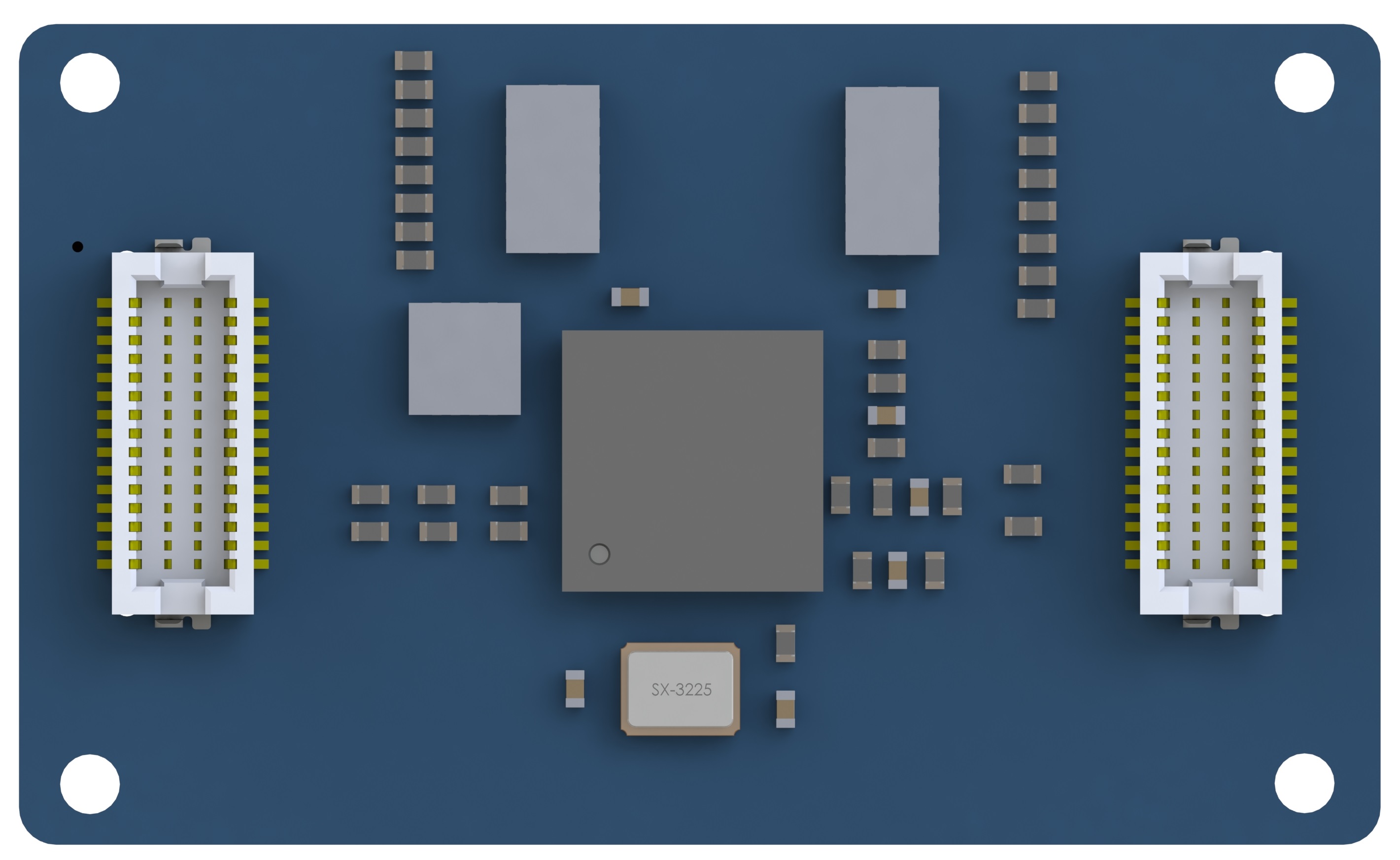
General Information:
- Layers: 8-layer PCB with 1 mm thickness.
- Dimension: 36 mm X 22 mm.
- Main processor: STM32F427AIH6.
- Necessary peripherals: minimum system, FRAM, I2C buffer, UART buffer, status LED, power regulator.
- Signals extended: 16X PWMs, 4X GPIOs, 6X power, I2C, CAN bus, 6 Serial ports, USB ports, SWD ports.
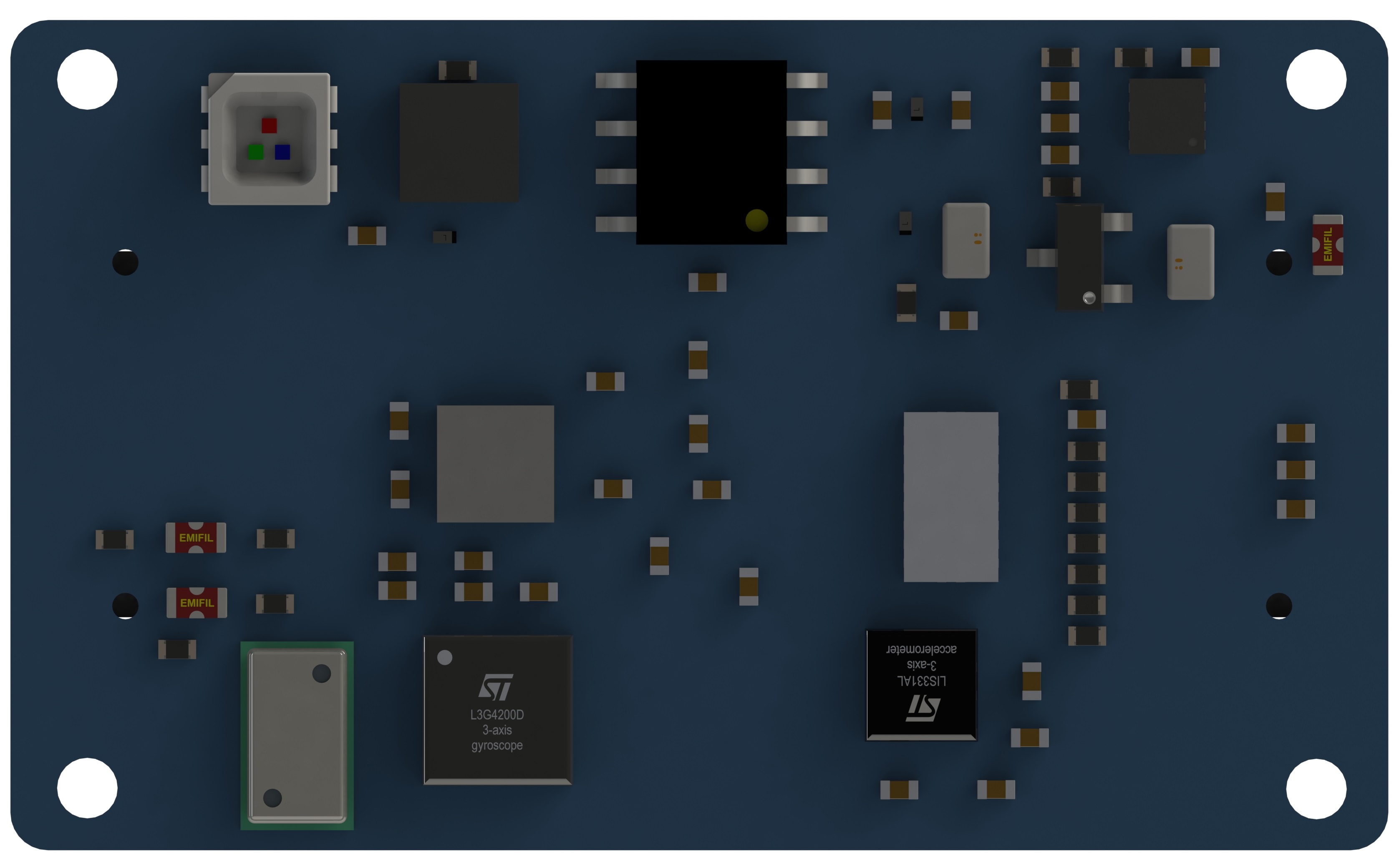
Sensors included:
- Gyroscopes: L3GD20;
- Acceleromters: MMA8452Q, LSM303D;
- Motion sensors: MPU6000, MPU6500, MPU9250;
- Magnetometers: HMC5883L, MPU9250, LSM303D;
- Barometers: MS5611-01BA, LPS22HB.
- Explanations: all of these sensors share SPI or I2C bus, drivers will be started on system initilized, data will be polled with necessary rates (gyro rates and accelerations will be at 800 or 1000 Hz, magenetometers will be queried with 100 Hz and altitude will be sampled at 50 Hz). Sensors can also be connected on the expandable ports.
Modules running:
- Sensor module: set all calibration parameters for opened sensors, obtain data from drivers output, combined all sensor data in one publishable topic;
- Commander module: processing regular events as status display, low voltage alarm, arm-disarm operations, switch control mode and navigation mode, decoding commands from GCS, broadcasting status information;
- Control modules: inner-loop attitude control module with composite nonlinear feedback method and output position control with robust perfect tracking method;
- Data logging: configurable data logging with desired rates and topics;
- Mission control: navigation mission control to specify mission elements, manage state machine and way-points.
- Base project: current firmware project is forked from the Pixhawk repo 3 years ago.
Motherboard
This motherboard extends the capabilities of the flight controller described in the above part. Besides providing power and extension signals to the flight controller, this motherboard got its own standalone functions. The current design works for quad-rotor, hexa-rotor and Y-3 configurations, with the pre-defined functions and shapes.
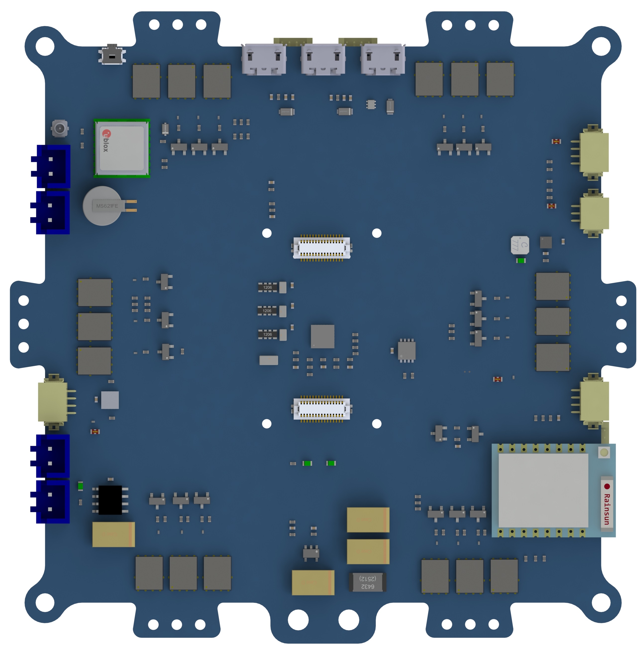
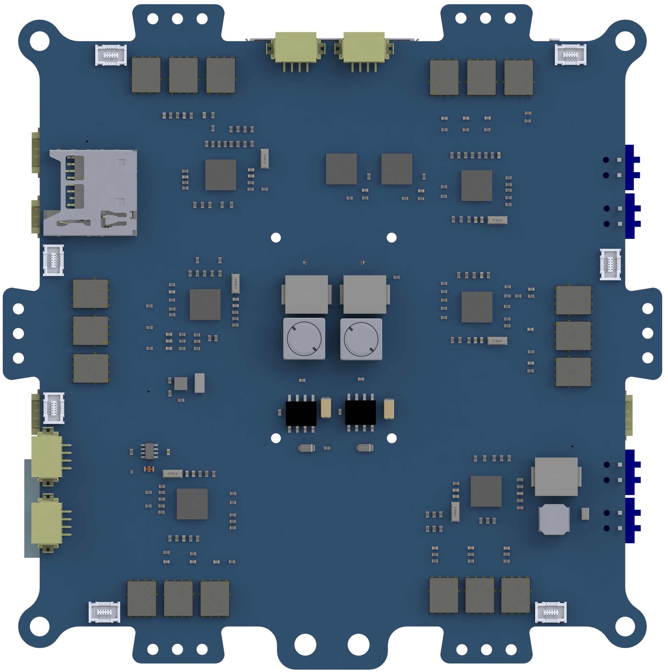
General Information:
- Layers: 6-layer PCB with 1 mm thickness.
- Dimension: 95 mm X 95 mm.
- Power rails: input 2-cell to 4-cell battery, output 12V/1A, dual 5V/4.5A and 3.3V/1A power.
Functions extended:
- GPS: integrated u-blox GPS m8 series receiver and antenna, with backup power supply.
- Serial to Wi-Fi device: ESP8266 based tiny serial to Wi-Fi module for data downloading and command uploading.
- S-bus receiver: compatible with Futaba S-bus receiver module.
- ESCs: 6X 3-phase brushless DC motor ESCs, which supports PWM command mode and I2C command mode. The ESC is also able to report its status including voltage, current, temperature, and rpm.
- Other necessary parts: level shifter, protocol shifters, voltage and current sensing, board to wire connectors, etc.
Modules running:
- Mavlink: communication module running on a specified UART prots and transmitted to GCS via serial to Wi-Fi device;
- Servo output: PWMs/I2C bus connected to ESCs to transmit commands from controller for servo output;
- PPM/S-bus: receiver input from RC transmitters, a UART device is allocated to S-bus input to decode the data, while PPM is a general timer function;
- Further peripherals: I2C bus will attached more devices (external magnetometers, range sensors, other MCUs), UART will be connected to upper-level CPU as Intel processor for more high level algorithm.
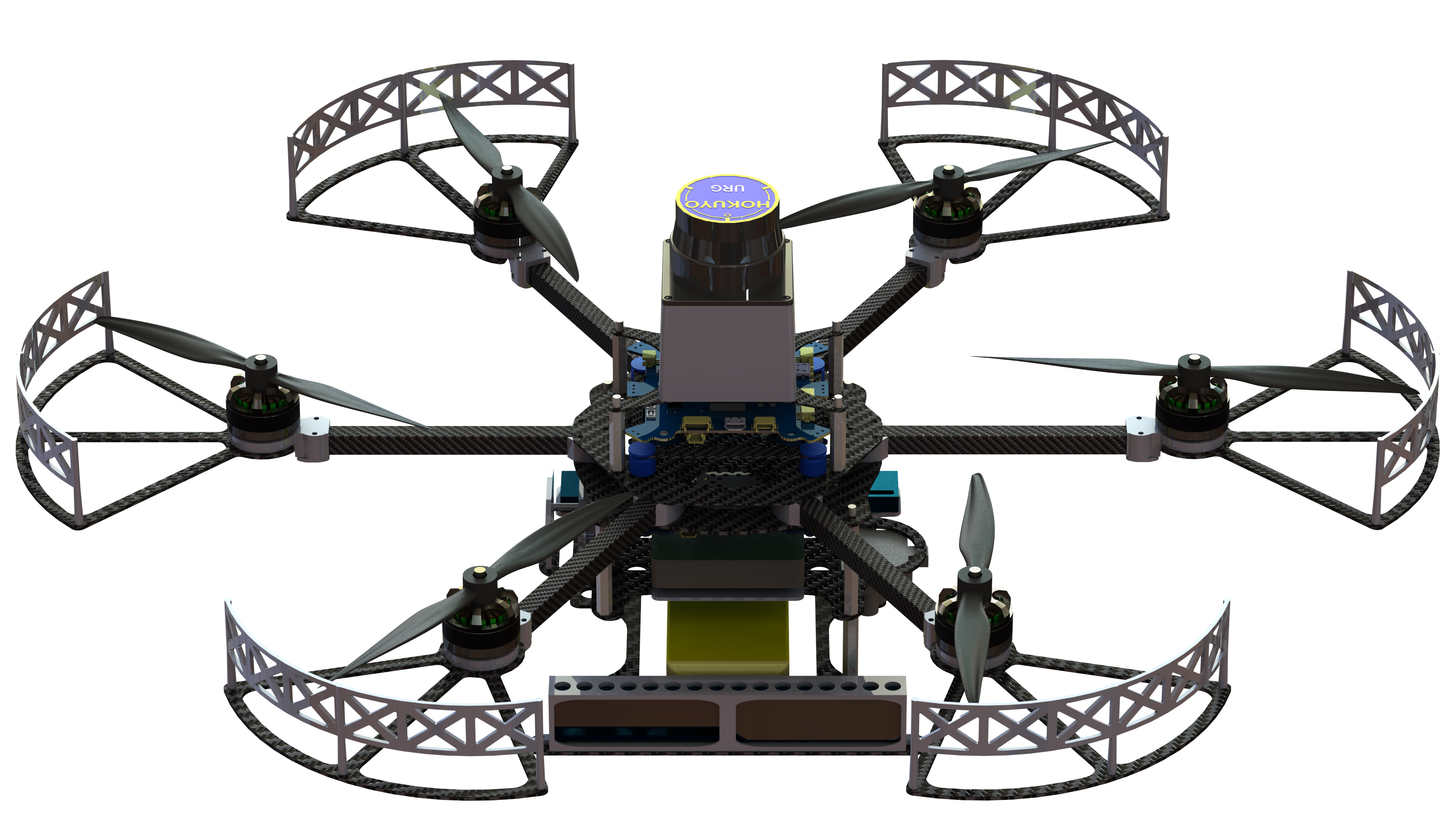
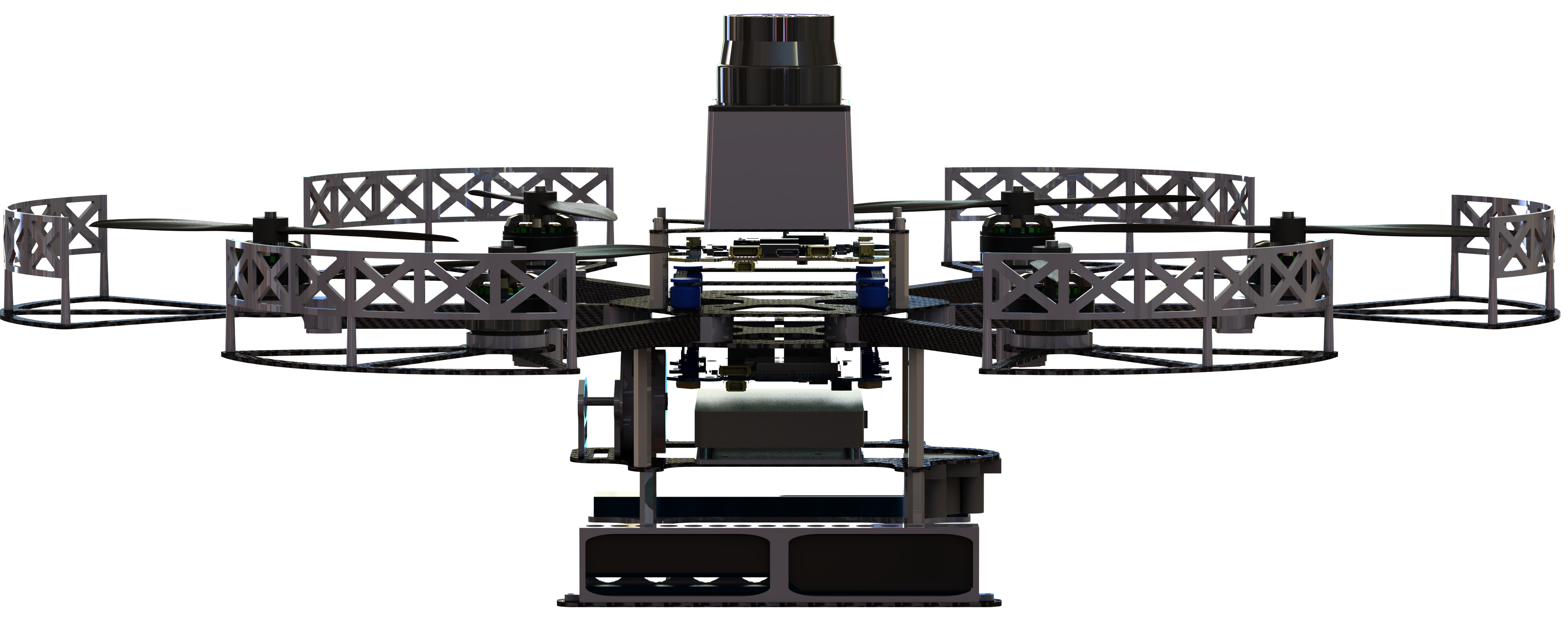
Platform Overview
Below figures shows the overall assembly effect of the platform INSTINCT. With the flight controller and mother board, the hexa-copter is able to perform GPS guided navigation. Design has been verified with real flight test data besides the lab.
Parameter table:
- Measured: several parameters are measured, as mass, dimension and beam length;
- Estimated: moment of inertia can be calculated with a simple experimental setup, i.e. 3-wire setup. Alternatively, they can be obtained with an estimated value from SolidWorks, given that density and mass of all components are correctly defined.
- Calculated: motor & propeller parameters are calculated with experiments, i.e. a tachometer and a pwm recorder to calculate motor steady state parameters, a load cell and a tachometer to calculate propeller thrust and torque parameters.
Controller stuff:
- Modeling: nonlinearity involved by the kinematic part is handled once the current attitude and reference attitude is known, by the thrust-vector orientation method. Output of this part will be the pure 6-DOF dynamics, which can be handled with a standard method, feedback linearation with the estimated gyro rates.
- Control: inner-loop attitude is controlled with a 200 Hz controller, which is realized with composite nonlinear feedback method. This method is suitable for fast dynamic plant for its high gain at large error and low gain at small error, that is to say, fast convergence rate at initial state and small overshoot when output is approaching reference. For outer loop, the robust perfect tracking method is used with an augmented plant definition.
Software Modules
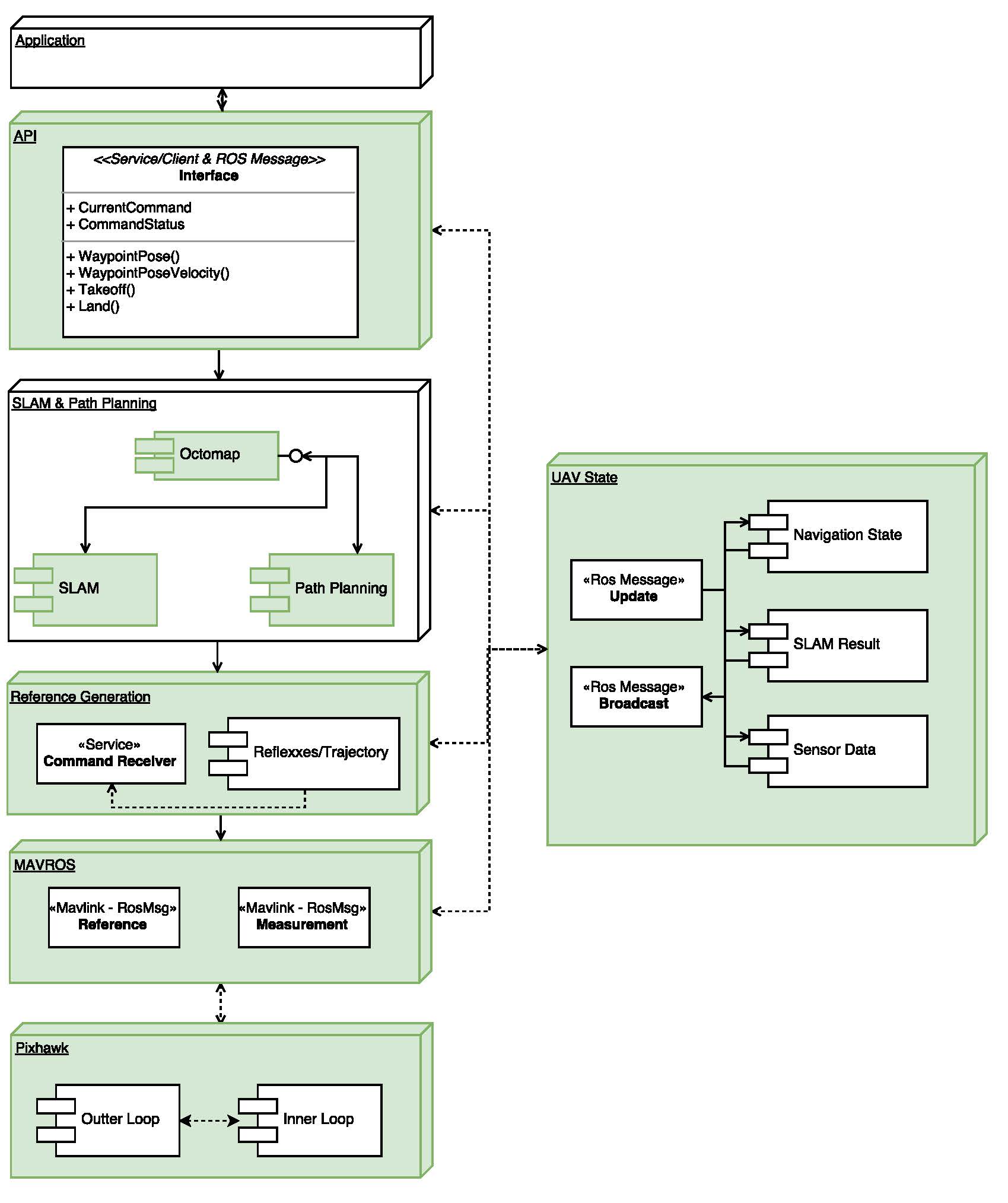
ROS Hierachy
Software is the core of the whole project, as the brain to a human. According to the platform, an Intel Up-board is the main CPU for higher level intelligence. The output of sensors laser scanner and front-facing RGBD-camera Intel Realsense, are all directed into Intel Up-board for further processing. Below video is the handheld platform with a Realsense camera. ORB-SLAM is running onboard on ROS kinetic version. For laser scanner, Google SLAM or hector SLAM is used for this project. The future work will be fusion of multiple software node pose estimation results, along with the inertia measurements.
Modules list:
- Flight controller firmware are processed on the MCU STM32F427, which necessary topics published to serial port and further to USB port of the upper level CPU.
- In the upper level CPU Up-board, the whole system is running on ROS in Ubuntu system. ROS nodes are inter-connected to share information.
- Application layer handles the user defined missions and state change conditions. The API layer defines necessary and basic functions such as takeoff and landing, fly to waypoint or fly a certain distance. SLAM and path planning layer includes the SLAM and planning nodes subscribing raw sensor information (laser scans and raw images) and publishing reference position points. Obstacle avoidance is also handled in this node where a local/global map is maintained for planning and loop closure purpose.
- MAVROS is the interface between ROS and MAV platform using protocol Mavlink.
FPGA Stereo Vision
Field programmable gate array extends the ability of image processing by parallel processing and line synchronization. We use Xlinix Zync7020 supporting for dual-cemera drivers with high resolution and image pre-processing. Depth map estimation based on epi-polar geometry and ORB feature extraction are developed on this module. Further development of communication between FPGA module and Intel Upboard is still under progress. This module will replace the Intel Realsense as the forward facing vision system. The large view angle and high frame rate will enable fast processing, i.e. fast flight capability in dynamic environment.
Sub-project1: SAFMC-2017
Introduction
The platform InstinCT is specially designed for GPS-denied environment navigation, catering for applications in unknown and realisitic scenarios. With different configuration of Lidar and visual sensors, we first demonstrated our capability in 2017 Singapore Amazing Flying Machine Competition category D2, the fully autonomous category, with the hexacopter drone performing autonomous navigation with a 30-meter Hokuyo laser range finder. This video shows the preparation of the competition, where all the efforts done are based on our group member’s research work, on mission management, lidar SLAM, path planning and trajectory generation, state fusion, communication, flight control, and hardware integration. Thanks to the integration of Google cartographer, a lidar based SLAM, providing high frequency updating rate, loop closure detection and low computational consumption.
Real Competition Scenario
The actual challenge includes several scoring points:
- autonomous take-off;
- entering building through window;
- flying through corridors;
- chemical sampling at an unknown location through visual detection;
- identify casualty’s name tag through on-board camera;
- enter and identifying personnel in dark room;
- passing through array of poles and a fan to emulate windy condition;
- visual guided precise landing.
The NUS UAV team completes all of the missions and awarded the championship.
Sub-project2: IMAV-2017
Coming soon…