Contents
- Flight Control System
- Electronic Speed Controller
- Optical Flow Module
- Gumstix on YOCTO Project
- Platform Overview
- Sub-project1: Banner-quad
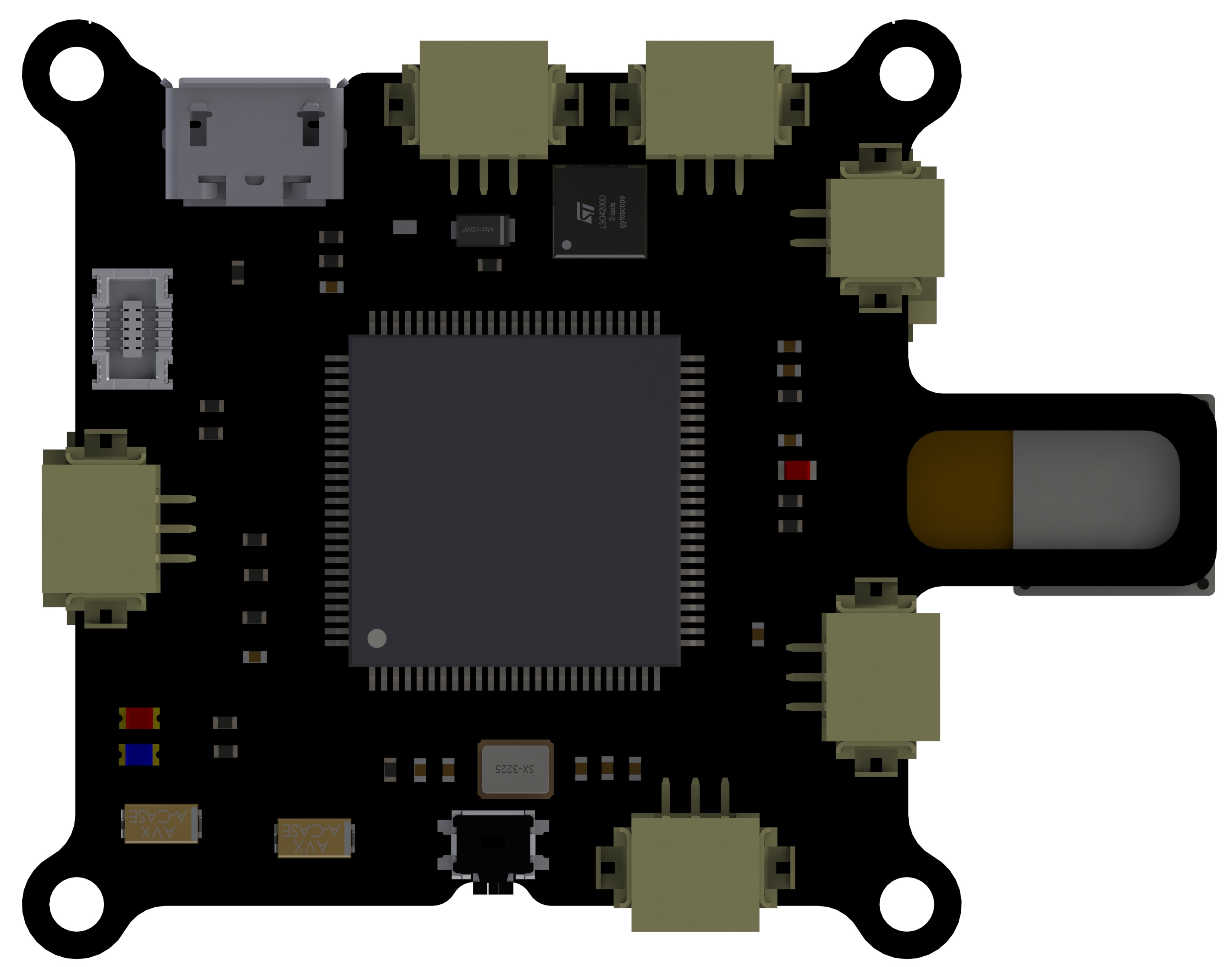
Flight Control System
This flight control module is the most optimized integration compared to the COTS products. The development duration expands for two years, where I improved the controller from the aspects of new functions, smaller footprints, EMC/EMI concerns, current inteference, signal reflection and oscillation. These signal integrity issues affects the performance of the signal as well as the lifttime of the components to a large extent.
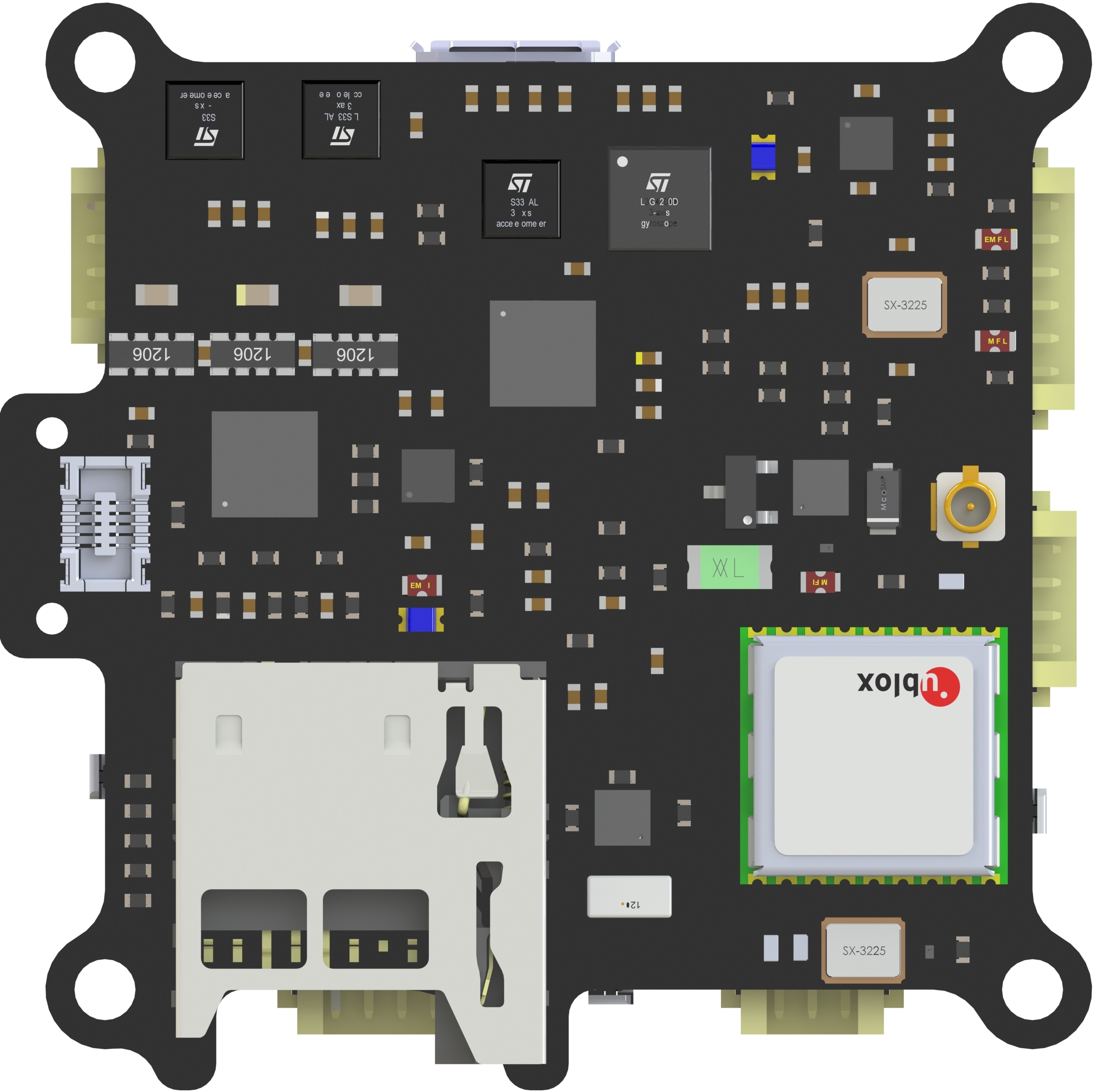
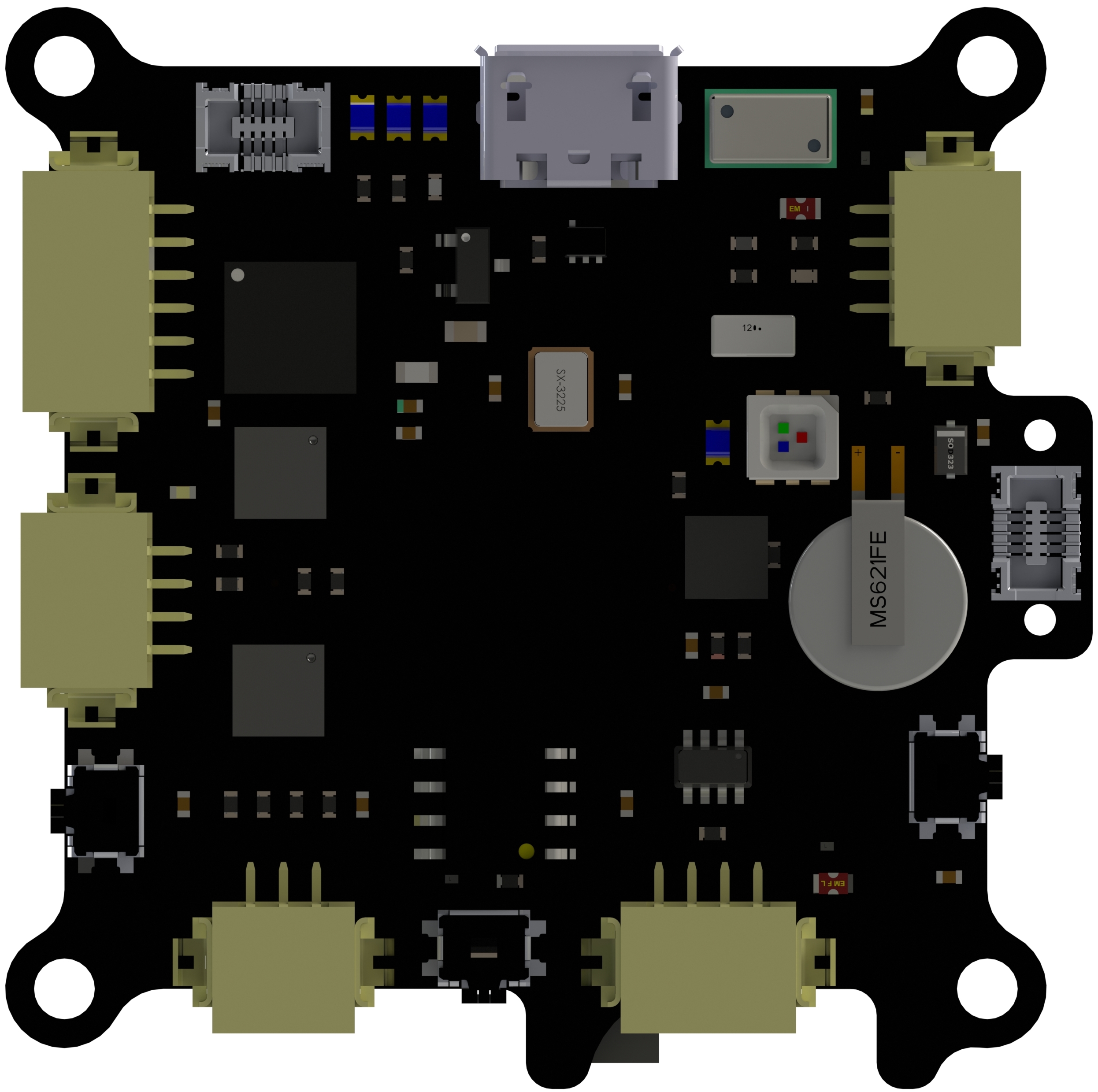
General Information
- Layers: 8-layer PCB with 1 mm thickness.
- Dimension: 35 mm X 35 mm.
- Main processor: STM32F427IIH6.
-
Necessary peripherals: minimum system, FRAM, I2C buffer, UART buffer, status LED, power regulator, power switcher, GPS ublox m8q, SD slot,
- Gyroscopes: L3GD20;
- Acceleromters: MMA8452Q, LSM303D;
- Motion sensors: MPU6000, MPU6500;
- Magnetometers: HMC5883L, LSM303D;
- Barometers: MS5611-01BA.
- Explanations: all of these sensors share SPI or I2C bus, drivers will be started on system initilized, data will be polled with necessary rates (gyro rates and accelerations will be at 800 or 1000 Hz, magenetometers will be queried with 100 Hz and altitude will be sampled at 50 Hz). Sensors can also be connected on the expandable ports.
Firmware Running
- Sensor module: set all calibration parameters for opened sensors, obtain data from drivers output, combined all sensor data in one publishable topic;
- Commander module: processing regular events as status display, low voltage alarm, arm-disarm operations, switch control mode and navigation mode, decoding commands from GCS, broadcasting status information;
- Control modules: inner-loop attitude control module with composite nonlinear feedback method and output position control with robust perfect tracking method;
- Data logging: configurable data logging with desired rates and topics;
- Mission control: navigation mission control to specify mission elements, manage state machine and way-points.
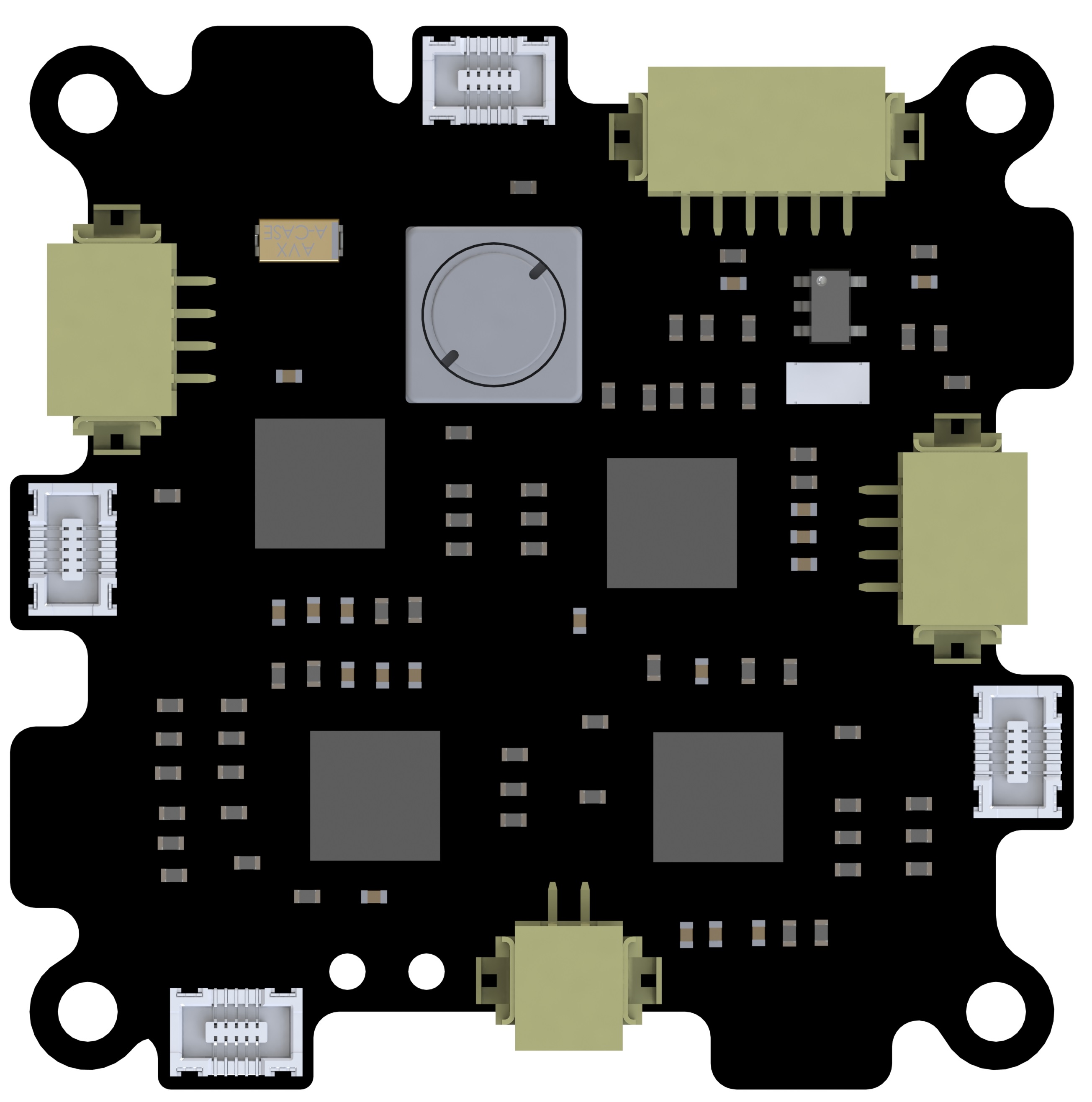
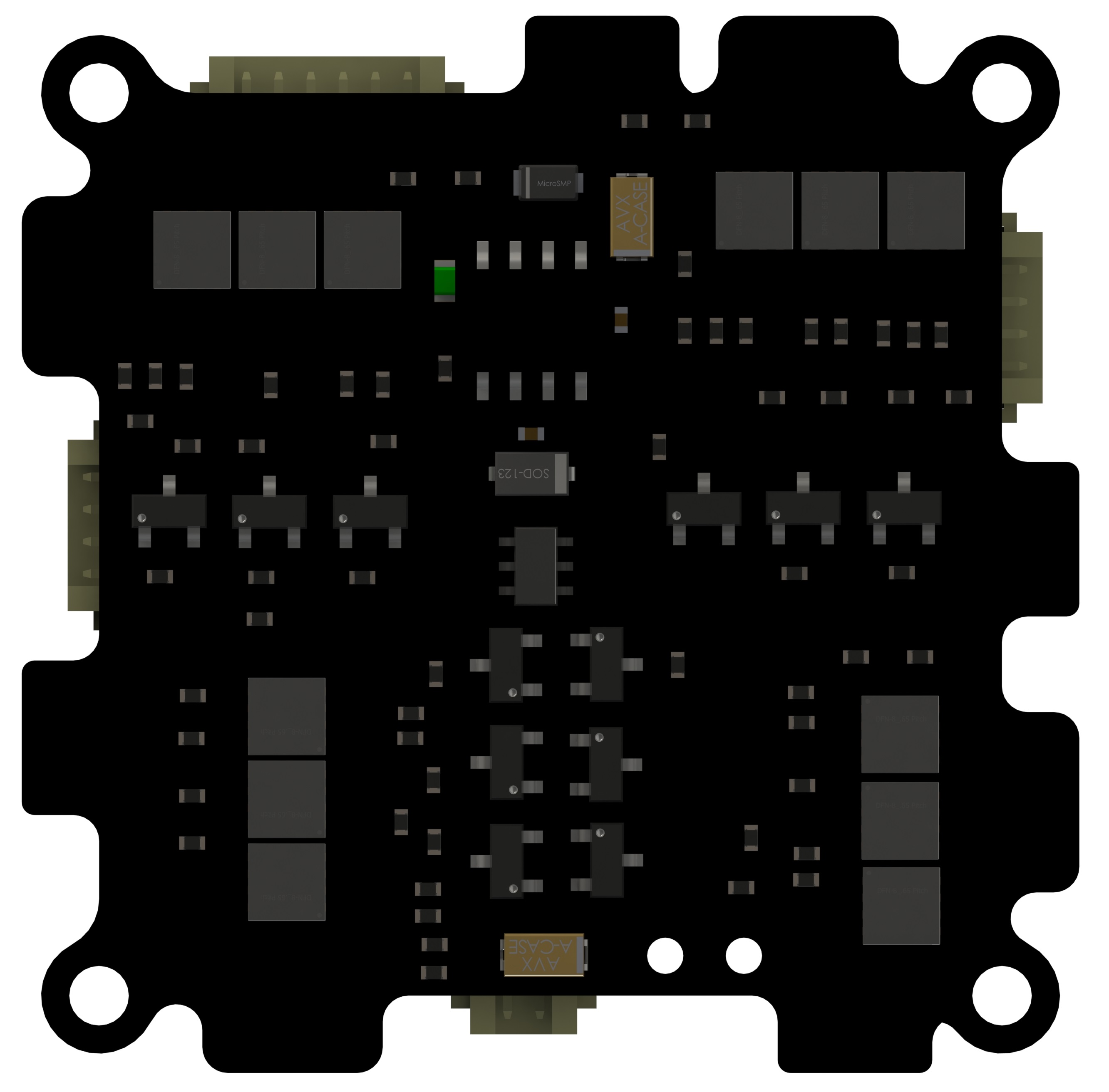
Electronic Speed Controller
This electronic speed controller receives command from PWM signal sent by flight control module and generates switching command to 6 power MOSFETs. These power MOSFETs serves as electrical switch to control the connectivity of each phase of the motor. A faster sequence will lead to faster RPM, and vice versa.
General Information
- Layers: 6-layer PCB with 1 mm thickness.
- Dimension: 35 mm X 35 mm.
- ESCs contained: 4 ESCs controlled by atmega8l.
- Necessary peripherals: battery power input and motor output, power ports for other modules.
ESC firmware
The ESC firmware is composed in Assembly language which is mainly forked from SimonK firmware. Several adapations were done to improve the input PWM width and add I2C for input and status output.
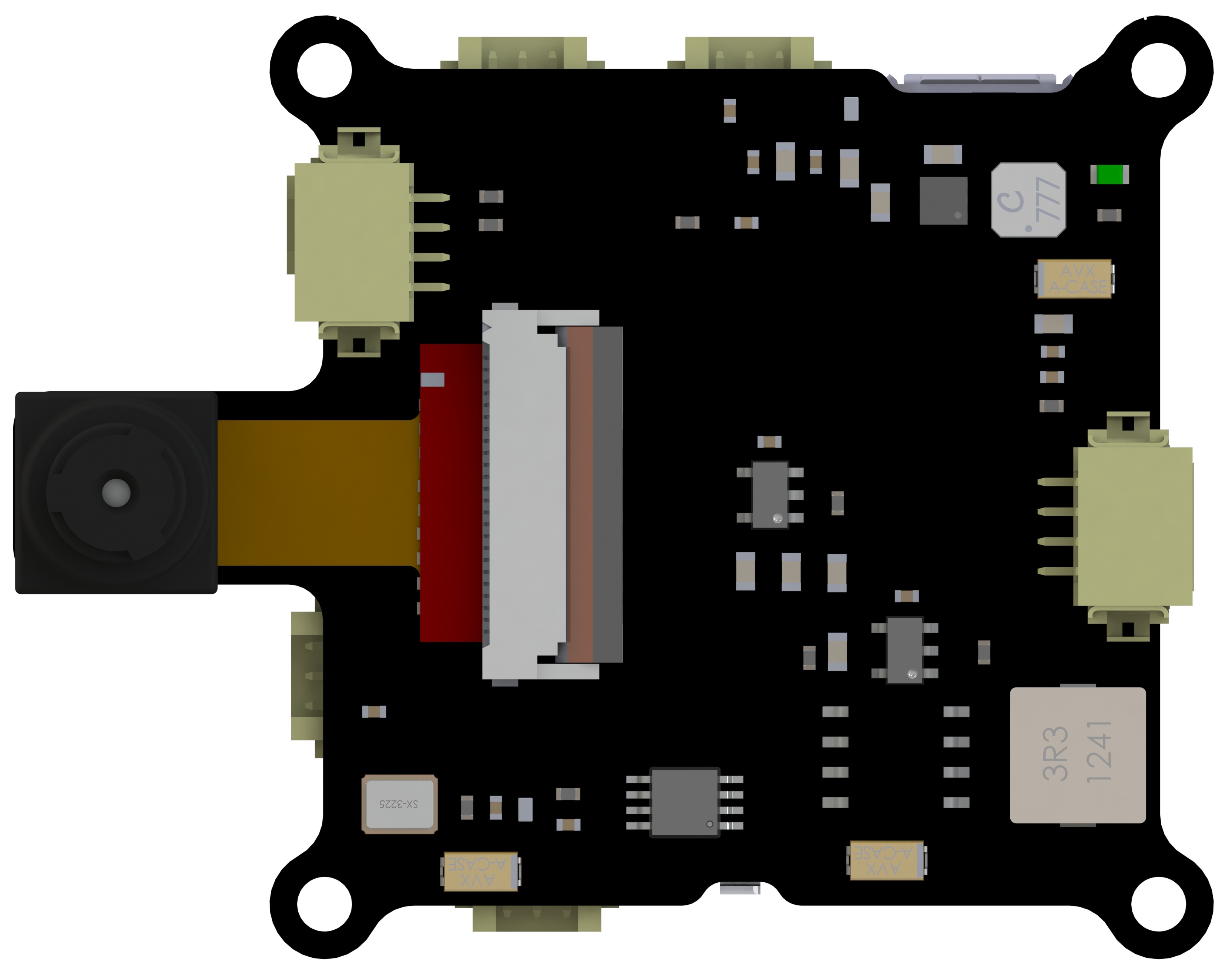
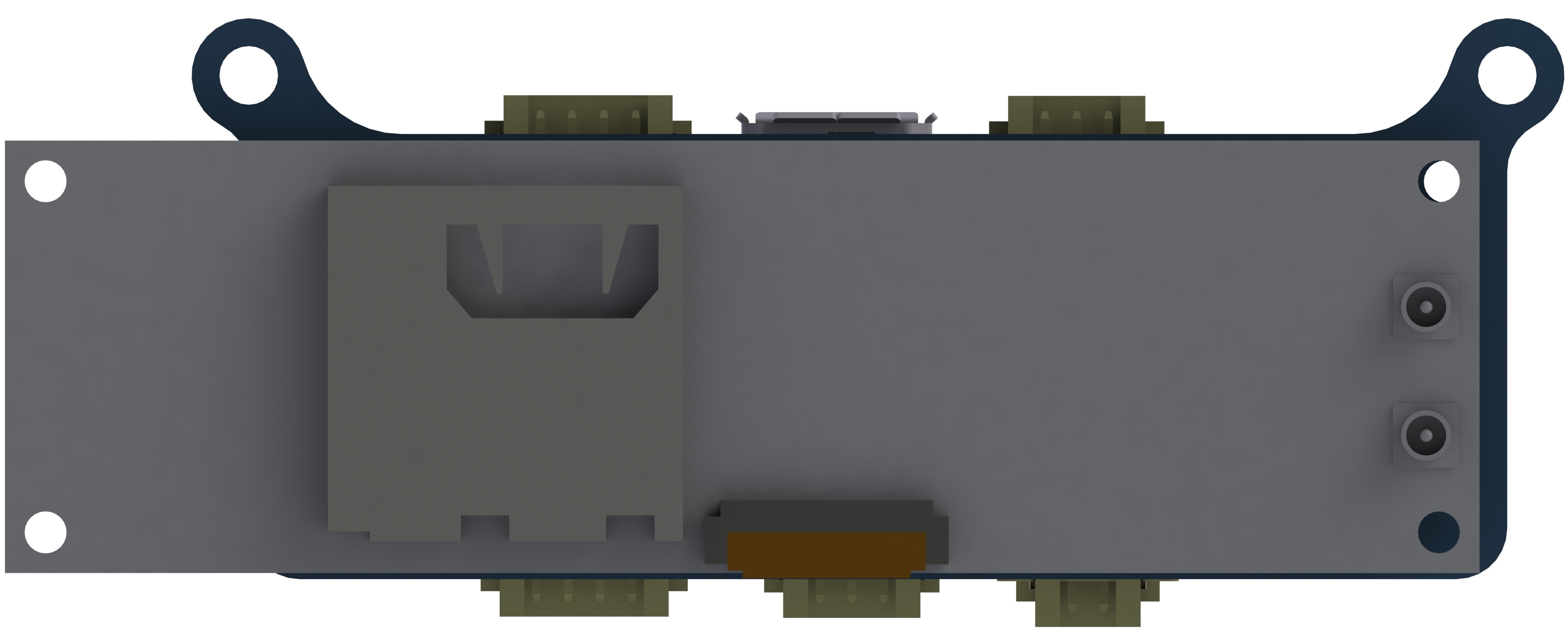
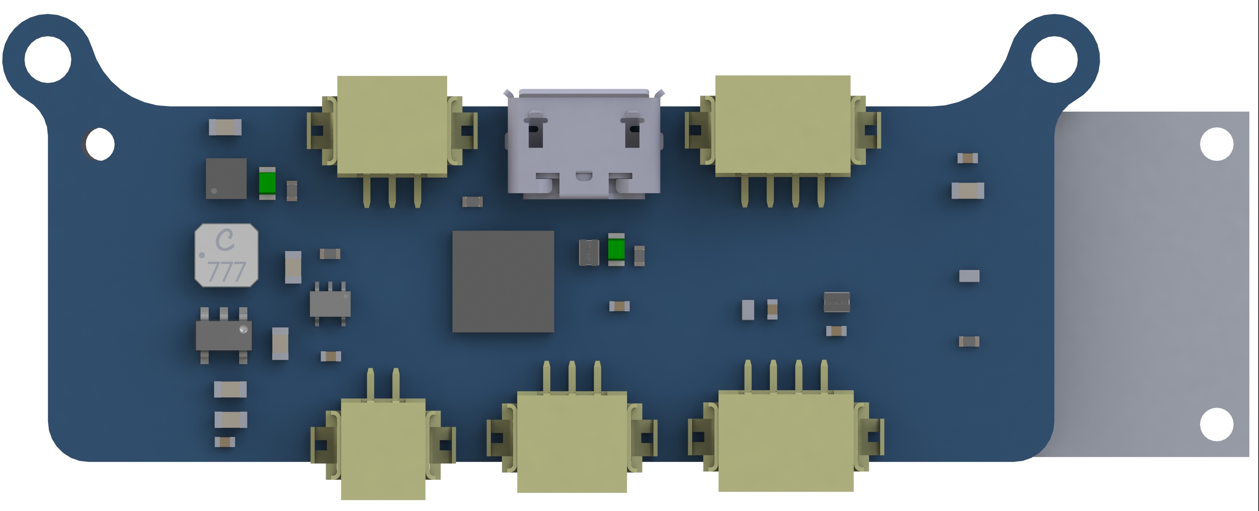
Optical Flow Module
The optical-flow is the pattern of apparent motion of objects, surfaces, and edges in a visual scene caused by the relative motion between an observer and a scene, which is imitation from the insect vision. This technique is now widely used in computer vision and robotics, mainly for estimation of lateral movements velocity.
Hardware Specs
- General info: a 6-layer PCB with dimension of 35 mm X 35 mm;
- Processor: STM32F407;
- Image sensor: OV9655;
- Other sensors: L3GD20 for gyroscope, Ultrasonic sensor for height detection, or Teraranger One for accurate large distance measurement.
Firmware Implementation
The firmware can be separate into two parts: drivers and algorithm. The driver part is more tricky for OV9655 as configurations of registers determines the resolution, fps, image format and other image features. With the DCMI interface enabled for the camera, a complicated scheme to swap the RAM area to stor and transmit images to GCS as a calibration and display tool is developed. Image transfer mainly uses DMA instead of RAM for faster speed. Drivers for other sensors are also necessary, which are SPI interface for gyro, uart interface for ultrasonic sensor and I2C interface for Teraranger One.
The optical flow algorithm utilizes the low-level assembly language for fast image process, which is mostly bit operation within memory. For flow detection, a low resolution image (64 X 64 pixels) was fed to the processor and first examined its feature point. The feature point is determined by the intensity change inside a sliding window. Similar feature points will be searched in their vicinity in the successive images with SAD block matching method. Flow information will be averaged throughout these feature point with histogram or normal mean.
Flow information will be further processed with gyro rate compenstation and height calibration, for the real velocity extraction.
Gumstix on YOCTO Project
In order to extend the computational capability and process more sensor input from external camera/laser scanner or range sensor, the above mentioned modules are not enought. However, to implement industrial grade process unit exceeds the weight budget far away. Thus, we selected the Gumstix Overo fire based on ARM cortex A9, with a dimension of 17mm X 58mm, for further processing power. I have designed an extension board for the Gumstix module to introduce its SPI/I2C and UART peripherals.
Firmware Implementation
Based on YOCTO project, I customized the embedded Linux system for Gumstix architecture. Most work to be done is at metadata layer of the Yocto project. These layers provide the three main functions: Metadata, which includes all the software/kernal codes that to be compiled; board support package (BSP) layer, which is to configure hardware, specifically is to provide the hardware support for Gumstix OMAP3530; Distro layer, which includes some configuration files and layer settings. After configuration for BSP, the only thing we need to do is wait for compilation and prepare a SD card for image and u-boot burning.
With an embedded Linux on the Gumstix, the applications developed for image transmission, path planning are able to follow the standard method. For real-time image transmission, I have integrated Gstreamer code into the multi-threading application.
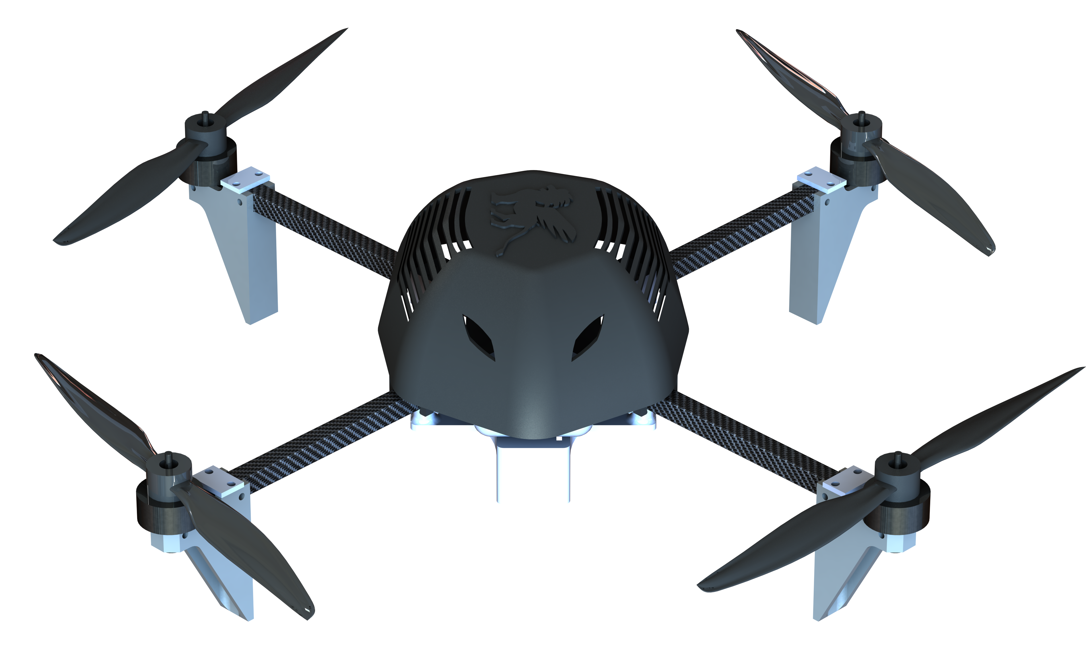
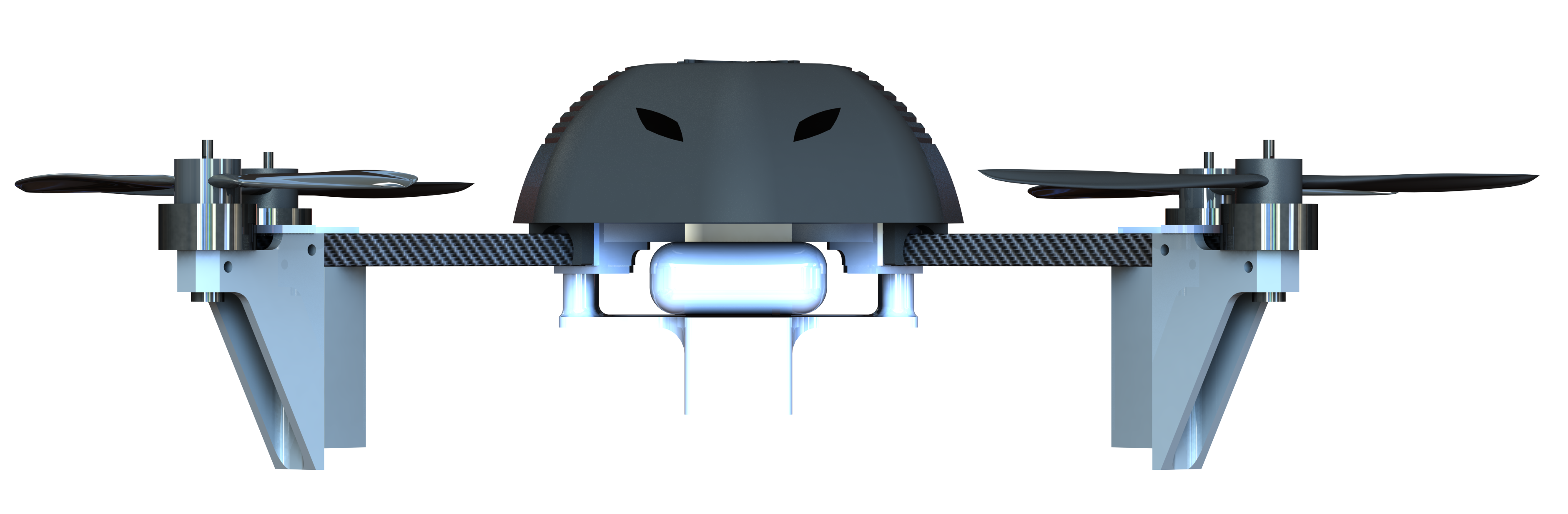
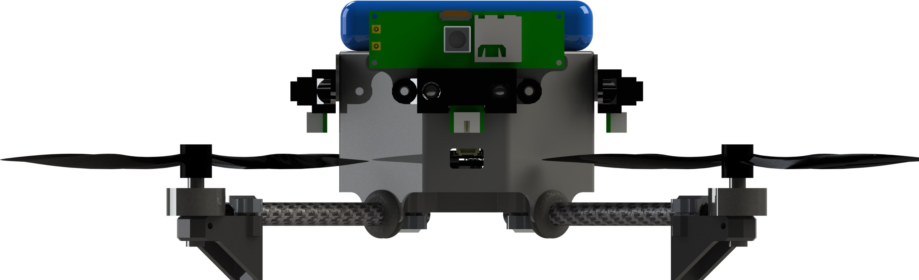
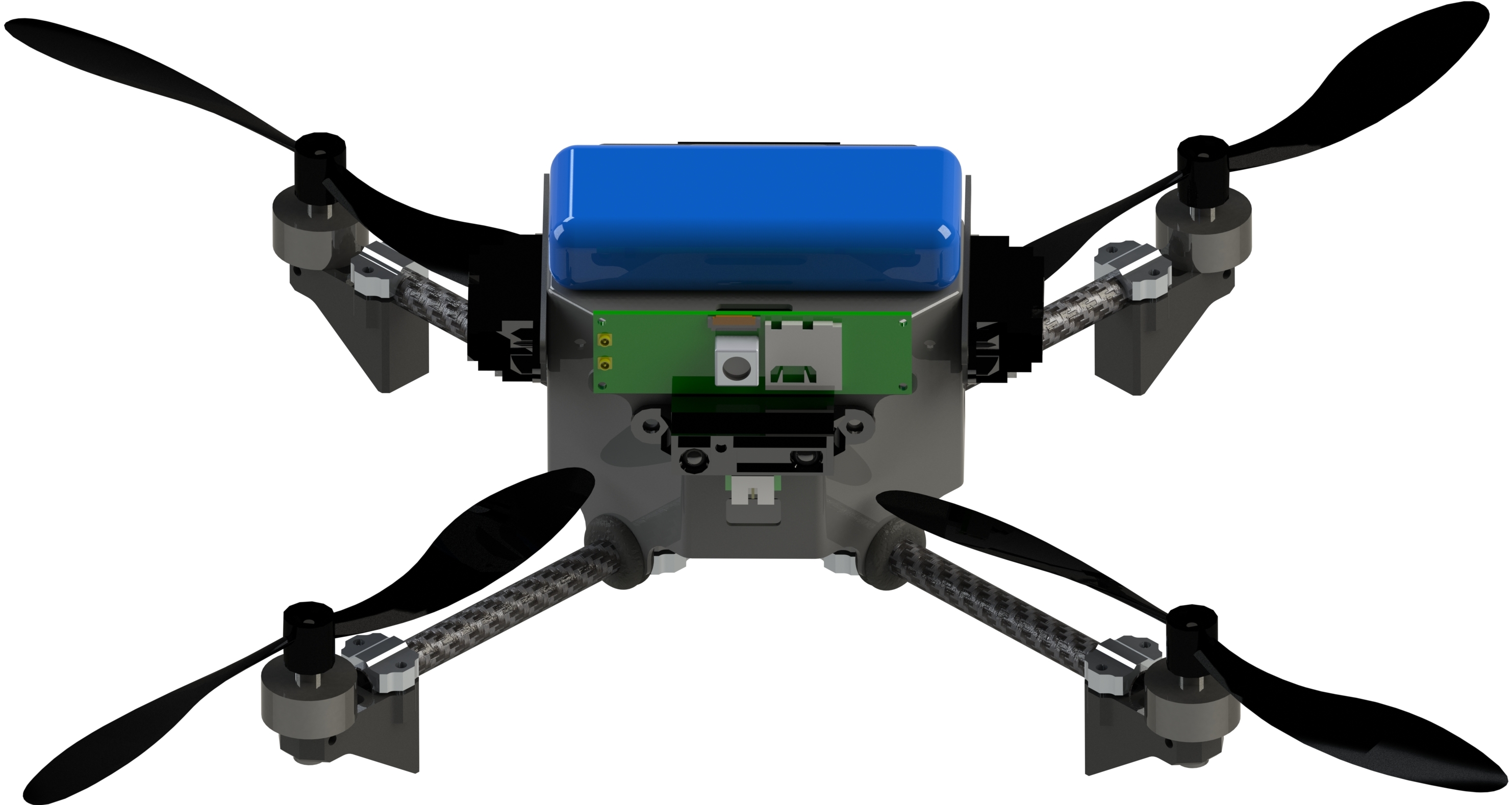
Platform Overview
The overall platform includes all the circuit modules with external sensors attached: ultrasonic modules, cameras, optical flow modules. The flight demo and detailed algorithm, SLAM and ROS integration can be found in my thesis and defense PPT, which is also avaiable in this website.
Sub-project1: Banner-quad
This is another side project, which use a similar module that is only able to perform GPS based navigation. The special feature for this platform is that it can drop a bannar from the mechanism mounted underneath the main structure with a metal-gear servo. This platform is usually used for demos or show for a special event.